

Welcome to our comprehensive guide on the various types of thyristors! Thyristors are essential semiconductor devices widely used in electronic circuits, power control systems, and communication applications. These devices exhibit unique properties that make them highly efficient for switching and controlling electric power. Understanding the different types of thyristors, much like understanding the Types of Amplifiers and Types of Multivibrators, is crucial for engineers, technicians, and anyone interested in electronics.
In this in-depth exploration, we will delve into the fundamental principles of thyristors and discuss their distinct characteristics and applications. From the classic silicon-controlled rectifiers (SCRs) to the more advanced gate turn-off thyristors (GTOs), and beyond to silicon-controlled switches (SCS), TRIACs, and more, we will unravel the functionalities of each type, similar to examining Types of Bridge Rectifiers and Types of Integrated Circuits.
As we navigate through the diverse world of thyristors, you will gain insights into their operational modes, triggering mechanisms, and how they contribute to enhancing the performance of various electronic systems. Whether you’re a seasoned professional or a curious enthusiast, our guide will cater to all levels of expertise and provide a solid foundation for your understanding of thyristor technology, just as exploring the Types of Bearings enhances mechanical knowledge.
So, let’s embark on this journey to discover the fascinating world of thyristors and explore their critical roles in powering our modern world!
Basics of Thyristors
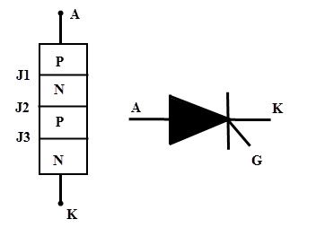
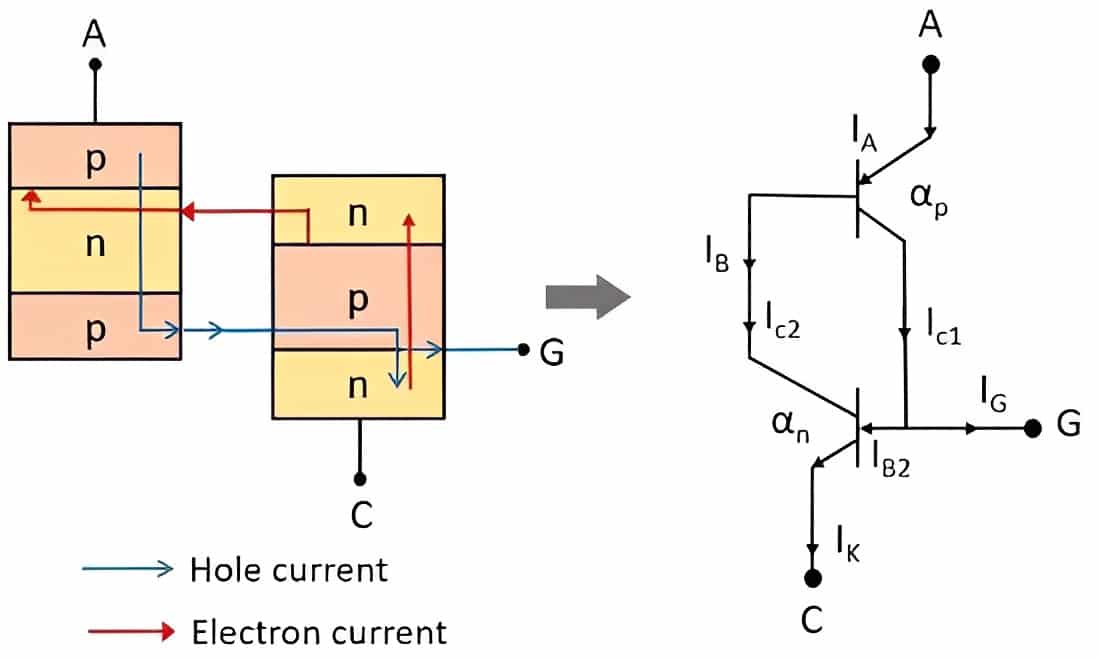
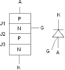
Thyristors are semiconductor devices that are used in high-power applications. They are made up of four layers of alternating P-type and N-type materials arranged in a specific order. The device has three terminals: anode, cathode, and gate. The anode is the positive terminal, the cathode is the negative terminal, and the gate is the control terminal. The thyristor acts as a bistable switch, conducting when the gate receives a current trigger and continuing to conduct until the voltage across the device is reverse-biased or until the voltage is removed by some other means. Thyristors can be understood with the help of two transistor analogies. The collector of one transistor is connected to the base of the second transistor while the collector of the second transistor is connected to the base of the first transistor. Thus, a total of four layers of semiconductor material are connected and a total of three junctions are formed. In thyristors, there are three ree terminalsthode and gate. The gate terminal provides the controlling voltage.
Thyristors are useful in switching applications because they can be fully on or off. This two-state capability differs from transistors, which operate in between on and off states, waiting for a signal to conduct current. Thyristors operate in one of the following three states, depending on the requirements: forward blocking mode, forward conducting mode, and reverse blocking mode. Thyristors are crucial power semiconductor devices. Due to their ability to rectify and switch, they find applications in power supplies for digital circuits, AC and DC motor speed controls, inverter circuits, oscillator circuits, chopper circuits, power switching circuits, relay replacement circuits, level-detector circuits, and many more.
Types of Thyristors
Here is a list of some common types of thyristors:
1. Silicon-Controlled Rectifier (SCR): Also known as a thyristor or reverse blocking triode (RBT), SCR is the most widely used and fundamental thyristor type. It is a four-layer, three-junction semiconductor device that allows current flow in one direction once triggered.
2. Gate Turn-Off Thyristor (GTO): GTO thyristors can be turned on and off through a gate signal. Unlike SCRs, they can also be turned off before the natural commutation point, making them more versatile for high-power applications.
3. Silicon-Controlled Switch (SCS): Similar to SCR, SCS also allows current flow in one direction, but it can be turned off by applying a negative voltage to the gate terminal.
4. Triode for Alternating Current (TRIAC): TRIACs are bidirectional thyristors capable of controlling AC power by conducting in both positive and negative half-cycles of the AC waveform.
5. Reverse Conducting Thyristor (RCT): RCT is a type of thyristor that integrates a reverse diode in the same package, allowing bidirectional current flow.
6. Gate-Assisted Turn-Off Thyristor (GATT): GATT thyristors combine the features of GTO and IGBT (Insulated Gate Bipolar Transistor) devices, offering improved turn-off capabilities.
7. MOS-Triggered Thyristor (MCT): MCTs utilize a MOSFET (Metal-Oxide-Semiconductor Field-Effect Transistor) to control the thyristor, resulting in fast switching and low power loss.
8. Light-Activated SCR (LASCR): LASCRs are triggered by light, making them suitable for optoelectronic applications.
9. Programmed Unijunction Transistor (PUT): Though not a typical thyristor, PUTs are often considered thyristor-like devices, and they find use in timing and triggering applications.
Each type of thyristor has its unique characteristics and applications, catering to specific requirements in electronic systems, power control, and beyond. Understanding these different types helps engineers and enthusiasts choose the most suitable thyristor for their specific projects. In what follows, a more detailed description of each type is presented.
Silicon-Controlled Rectifier (SCR)
The Silicon-Controlled Rectifier (SCR) is a crucial semiconductor device widely used in various electronic and power control applications. Also known as a thyristor or reverse blocking triode (RBT), the SCR plays a vital role in converting alternating current (AC) into direct current (DC) and controlling the power flow in a circuit. In this section, we will explore the fundamental principles and construction of SCR.
Construction and Working Principles
The SCR is a four-layer, three-junction semiconductor device that operates as a bistable switch. It consists of three semiconductor regions: the P-type anode, the N-type cathode, and the N-type gate. The junctions between these regions create two P-N junctions, represented as P1-N1 and P2-N2. When a positive voltage is applied to the anode terminal concerning the cathode terminal, the P1-N1 junction becomes forward-biased, allowing current to flow through the SCR.
Rectification Process
One of the primary functions of the SCR is rectification, converting AC into DC. The SCR acts as a unidirectional switch that conducts current only when a triggering signal is applied to its gate terminal. Once triggered, the SCR remains in the ON state, allowing current to flow through the anode-cathode circuit until the current drops below a specified level or an external circuit interrupts it.
SCR Turn-On and Turn-Off Mechanisms
The SCR can be turned on through various methods, such as applying a positive voltage pulse to the gate terminal, injecting a current into the gate, or utilizing optoelectronic triggering through light (LASCR). The gate signal initiates the conduction process, and the SCR stays conducting even after the gate signal is removed.
Turning off the SCR is achieved by reducing the anode current below the holding current level, which causes the device to return to its non-conducting state. Alternatively, for faster turn-off, a reverse voltage can be applied to the anode-cathode circuit, effectively extinguishing the SCR’s conduction.
Applications of SCR
SCRs find extensive applications in a wide range of fields due to their robustness and efficiency. Some common applications include:
- AC-to-DC power rectification in power supplies and battery chargers.
- Motor control in industrial automation systems and motor drives.
- Voltage regulation in electronic dimmer circuits for lighting controls.
- Overcurrent protection and short-circuit protection in electronic circuits.
- Power control and phase-angle firing in high-power devices.
Advantages and Limitations
SCRs offer several advantages, including high current-carrying capacity, low cost, and simple control mechanisms. They are also highly reliable and can handle high-voltage and high-current applications. However, SCR devices have certain limitations, such as limited controllability during the ON state, and they are unsuitable for high-frequency switching applications.
Gate Turn-Off Thyristor (GTO)
The Gate Turn-Off Thyristor (GTO) is an advanced semiconductor device that belongs to the thyristor family. GTOs offer enhanced control capabilities, allowing them to be turned on and off using gate signals. This unique feature sets them apart from traditional thyristors like the Silicon-Controlled Rectifier (SCR). In this section, we will delve into the construction, working principle, and advantages of GTOs.
Construction and Working Principles
The GTO shares some structural similarities with the SCR, comprising three semiconductor regions: the P-type anode, the N-type cathode, and the N-type gate. However, it is designed with an additional N-type layer known as the “N-base” between the gate and cathode. This N-base layer enables gate control over the GTO’s conduction.
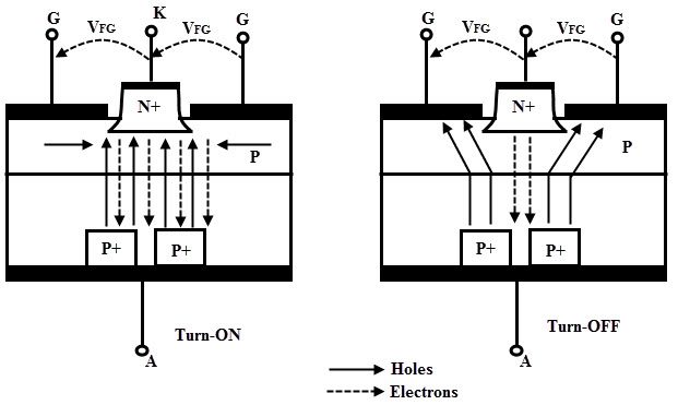
The GTO’s operation involves four modes: blocking, turn-on, conduction, and turn-off. In the blocking state, the anode voltage is lower than the cathode voltage, and the device does not conduct. Upon applying a positive voltage to the gate terminal, the N-base is flooded with charge carriers, causing the P1-N1 junction to become forward-biased and initiate the turn-on process. Once triggered, the GTO enters the conduction mode, and current flows through the anode-cathode circuit. To turn off the GTO, a negative voltage pulse is applied to the gate, which removes charge carriers from the N-base and interrupts the conduction.
Turn-Off Mechanism
One of the significant advantages of GTOs is their ability to be turned off by a gate signal. Unlike SCRs that need a reduction in current to turn off, GTOs can be turned off rapidly even when carrying a high current. This characteristic makes them suitable for high-power and high-frequency applications where fast switching is required.
Applications of GTO
GTOs find extensive use in various power control and high-voltage applications, including:
- Motor drives and speed control systems for industrial machinery.
- High-power inverters are used in renewable energy systems like wind turbines and solar power plants.
- HVDC (High Voltage Direct Current) transmission systems for efficient long-distance power transmission.
- Induction heating systems for industrial processes.
- Controlled power supply units in electric locomotives and traction systems.
Advantages and Limitations
GTOs offer several advantages over conventional thyristors, including:
- Rapid turn-off capability: GTOs can be switched off quickly, enabling better control and efficiency in high-power applications.
- Enhanced controllability: The gate signal allows precise control over the GTO’s conduction, making them versatile in various power control scenarios.
- Lower switching losses: Faster turn-off reduces switching losses, contributing to higher overall efficiency.
However, GTOs also have some limitations, such as higher gate drive power requirements and the possibility of triggering errors if not handled properly.
Silicon-Controlled Switch (SCS)
The Silicon-Controlled Switch (SCS) is a type of thyristor that shares some similarities with the more widely known Silicon-Controlled Rectifier (SCR). However, the SCS has a unique feature that sets it apart—it can be turned off by applying a negative voltage to its gate terminal. In this section, we will explore the construction, working principle, and applications of the SCS.
Construction and Working Principles
The SCS has a similar basic structure to the SCR, consisting of three semiconductor regions: the P-type anode, the N-type cathode, and the N-type gate. Like the SCR, it also features two P-N junctions (P1-N1 and P2-N2). The primary difference lies in the operation of the gate terminal.
When a positive voltage is applied to the anode terminal concerning the cathode terminal, the P1-N1 junction becomes forward-biased, initiating current flow through the SCS. However, unlike the SCR, the SCS can be turned off during conduction by applying a negative voltage to the gate terminal. This negative gate voltage creates a reverse bias across the P1-N1 junction, which interrupts the conduction and turns off the SCS.
Turn-On and Turn-Off Mechanisms
To turn on the SCS, a positive voltage pulse is applied to the gate terminal, triggering the device into the conducting state. Once triggered, the SCS remains conducting until it is turned off either by reducing the anode current below the holding current level or by applying a negative voltage to the gate terminal.
The ability to turn off the SCS through gate control provides added flexibility in certain applications, as it allows for more precise control over the switching process.
Applications of SCS
SCS devices find application in various electronic circuits and power control systems, including:
- Overcurrent protection: SCS devices can be used to protect circuits from excessive current flow by providing a means to interrupt current when necessary.
- Power control: SCS devices can be employed in applications that require variable power control, such as in lighting systems, heating elements, and motor control circuits.
- Solid-state relays: SCS-based solid-state relays offer advantages over traditional mechanical relays, such as faster response times and longer lifespan.
Advantages and Limitations
SCS devices offer several advantages, such as:
- Gate control for turn-off: The ability to turn off the SCS through the gate terminal provides enhanced control in certain applications.
- Compact size: SCS devices are relatively small and can be integrated into space-constrained electronic systems.
However, SCS devices also have some limitations, including:
- Limited voltage and current ratings: Compared to other thyristor types, SCS devices may have lower voltage and current ratings.
- Complexity in gate drive: The gate drive circuitry requires careful design to ensure proper turn-on and turn-off operations.

Triode for Alternating Current (TRIAC)
The Triode for Alternating Current (TRIAC) is a specialized semiconductor device that belongs to the thyristor family. Unlike conventional thyristors, TRIACs are bidirectional devices, capable of controlling the flow of current in both positive and negative half-cycles of an alternating current (AC) waveform. In this section, we will explore the construction, working principle, and applications of TRIACs.
Construction and Working Principles
The TRIAC comprises four layers of alternating P-type and N-type semiconductor material, forming three junctions: P1-N1, N1-P2, and P2-N2. This symmetrical structure allows the TRIAC to conduct current in both directions. Additionally, the TRIAC has a gate terminal that enables control over its conduction.
To turn on the TRIAC, a positive gate voltage is applied, causing the P1-N1 junction to become forward-biased in either the positive or negative half-cycle of the AC waveform, depending on the polarity of the gate signal. Once triggered, the TRIAC conducts current, and it remains conductive even after the gate signal is removed until the current falls below a specified holding current level or the AC voltage crosses zero.
Bidirectional Conduction
One of the primary advantages of TRIACs is their bidirectional conduction capability. Unlike other thyristors that can only control current in one direction, TRIACs can handle both positive and negative half-cycles of AC, making them suitable for AC power control applications.
Applications of TRIAC
TRIACs are widely used in various AC power control applications, including:
- Light dimmers: TRIAC-based dimmer circuits are commonly used to adjust the brightness of incandescent and halogen lamps, allowing users to control the intensity of lighting.
- AC motor speed control: TRIACs can be used to regulate the speed of AC motors in household appliances like fans and mixers.
- Heating control: TRIACs are utilized in temperature control systems for electric heating elements, providing precise regulation of heat output.
- AC power switches: TRIAC-based solid-state relays are employed in applications where rapid switching of AC power is required.
Advantages and Limitations
TRIACs offer several advantages, including:
- Bidirectional conduction: The ability to handle both positive and negative half-cycles of AC makes TRIACs versatile for various AC power control scenarios.
- Simple control: TRIACs can be triggered using a gate signal, allowing for straightforward and efficient control over AC power.
However, TRIACs also have certain limitations, such as:
- Snubber circuit requirement: TRIACs may require snubber circuits to prevent false triggering or voltage spikes during switching operations.
- Voltage and current limitations: TRIACs are not ideal for high-power and high-voltage applications due to their lower voltage and current ratings compared to other power devices.

Reverse Conducting Thyristor (RCT)
The Reverse Conducting Thyristor (RCT) is a specialized semiconductor device that combines the functionalities of a thyristor and a diode within a single package. Unlike conventional thyristors, the RCT can conduct current not only in the forward direction (anode to cathode) like a standard thyristor but also in the reverse direction (cathode to anode) like a diode. In this section, we will explore the construction, working principle, and applications of Reverse Conducting Thyristors.
Construction and Working Principles
The Reverse Conducting Thyristor (RCT) is designed with a symmetrical structure comprising four semiconductor layers: P-type anode, N-type anode, P-type cathode, and N-type cathode. This unique construction enables bidirectional conduction capabilities.
In the forward direction, when a positive voltage is applied to the anode concerning the cathode, the P-N junctions in the anode-cathode path become forward-biased, allowing the RCT to conduct current like a typical thyristor.
In the reverse direction, when a negative voltage is applied to the cathode concerning the anode, the P-N junctions in the cathode-anode path become forward-biased, and the RCT starts to conduct current like a diode.
Bidirectional Conduction
The most significant advantage of Reverse reverse-conducting thyristors is their bidirectional conduction capability. They can conduct current in both the forward and reverse directions, making them suitable for applications where bidirectional switching and control are required.
Applications of RCT
Reverse Reverse-conducting thyristors find applications in various electronic and power control systems, including:
- AC/DC converters: RCTs are used in AC/DC converter circuits that require bidirectional current flow and need to switch between rectification and inversion modes.
- Motor drives: RCTs are utilized in motor control circuits that require both forward and reverse rotation of motors, such as in robotics and industrial machinery.
- Regenerative braking: RCTs are employed in regenerative braking systems, which convert the kinetic energy of vehicles into electrical energy during braking.
Advantages and Limitations
Reverse Reverse-conducting thyristors offer several advantages, including:
- Bidirectional conduction: The capability to conduct current in both directions makes RCTs suitable for various bidirectional power control applications.
- Space-saving: Combining the functionalities of a thyristor and a diode in one package saves space and simplifies circuit design in some applications.
However, RCTs also have certain limitations, such as:
- Higher cost: RCTs may be more expensive than standard thyristors or diodes due to their combined functionalities.
- Limited voltage and current ratings: RCTs may have lower voltage and current ratings compared to some discrete thyristors or diodes.

Gate Assisted Turn-Off Thyristor (GATT)
The Reverse Conducting Thyristor (RCT) is a specialized semiconductor device that combines the functionalities of a thyristor and a diode within a single package. Unlike conventional thyristors, the RCT can conduct current not only in the forward direction (anode to cathode) like a standard thyristor but also in the reverse direction (cathode to anode) like a diode. In this section, we will explore the construction, working principle, and applications of Reverse Conducting Thyristors.
Construction and Working Principles
The Reverse Conducting Thyristor (RCT) is designed with a symmetrical structure comprising four semiconductor layers: P-type anode, N-type anode, P-type cathode, and N-type cathode. This unique construction enables bidirectional conduction capabilities.
In the forward direction, when a positive voltage is applied to the anode concerning the cathode, the P-N junctions in the anode-cathode path become forward-biased, allowing the RCT to conduct current like a typical thyristor.
In the reverse direction, when a negative voltage is applied to the cathode concerning the anode, the P-N junctions in the cathode-anode path become forward-biased, and the RCT starts to conduct current like a diode.
Bidirectional Conduction
The most significant advantage of Reverse reverse-conducting thyristors is their bidirectional conduction capability. They can conduct current in both the forward and reverse directions, making them suitable for applications where bidirectional switching and control are required.
Applications of RCT
Reverse Reverse-conducting thyristors find applications in various electronic and power control systems, including:
- AC/DC converters: RCTs are used in AC/DC converter circuits that require bidirectional current flow and need to switch between rectification and inversion modes.
- Motor drives: RCTs are utilized in motor control circuits that require both forward and reverse rotation of motors, such as in robotics and industrial machinery.
- Regenerative braking: RCTs are employed in regenerative braking systems, which convert the kinetic energy of vehicles into electrical energy during braking.
Advantages and Limitations
Reverse Reverse-conducting thyristors offer several advantages, including:
- Bidirectional conduction: The capability to conduct current in both directions makes RCTs suitable for various bidirectional power control applications.
- Space-saving: Combining the functionalities of a thyristor and a diode in one package saves space and simplifies circuit design in some applications.
However, RCTs also have certain limitations, such as:
- Higher cost: RCTs may be more expensive than standard thyristors or diodes due to their combined functionalities.
- Limited voltage and current ratings: RCTs may have lower voltage and current ratings compared to some discrete thyristors or diodes.
MOS-Triggered Thyristor (MCT)
The Mos-triggered thyristor (MCT) is a specialized semiconductor device that combines the characteristics of a thyristor with the control capabilities of a Metal-Oxide-Semiconductor Field-Effect Transistor (MOSFET). MCTs are designed to provide fast switching and low power loss in high-power applications. In this section, we will explore the construction, working principle, and advantages of MOS-Triggered Thyristors.
Construction of MCT
The Mos-triggered thyristor (MCT) consists of four semiconductor layers: P-type anode, N-type drift region, P-type base, and N-type cathode. Additionally, an insulated gate structure is integrated into the device, similar to a MOSFET. This gate allows for precise control over the MCT’s turn-on and turn-off processes.
Working Principle
The operation of the MCT involves three modes: blocking, turn-on, and conduction.
In the blocking state, no current flows between the anode and cathode. To initiate the turn-on process, a positive voltage is applied to the gate terminal. This creates an inversion layer in the N-type drift region, reducing the thickness of the drift region. As a result, the electric field is enhanced, allowing electrons to flow from the N-type cathode to the P-type base, triggering the thyristor action.
Once the MCT is turned on, the current flows freely between the anode and cathode, similar to a conventional thyristor, until the external circuit interrupts the current or the current drops below the holding current level.
Advantages of MCT
Mos-triggered thyristors offer several advantages over traditional thyristors and MOSFETs:
- Fast switching speed: The MOSFET-like gate structure enables rapid turn-on and turn-off times, making MCTs ideal for high-frequency applications.
- Low power loss: MCTs have lower conduction losses compared to conventional thyristors, leading to improved overall efficiency in high-power systems.
- High-voltage capability: MCTs are designed to handle high-voltage applications, making them suitable for power transmission and distribution systems.
Applications of MCT
Mos-triggered thyristors are used in various high-power applications, including:
- High-frequency inverters: MCTs find use in high-frequency inverters for induction heating, motor drives, and renewable energy systems.
- Power electronics: MCTs are employed in power converters, voltage regulators, and switch-mode power supplies for efficient energy conversion.
- High-voltage systems: MCTs are utilized in high-voltage direct current (HVDC) transmission systems for long-distance power transmission.
Limitations and Considerations
While MCTs offer significant advantages, they also have some limitations and considerations:
Gate voltage requirement: MCTs require a gate voltage to trigger the device, which necessitates a well-designed gate driver circuit.
Complexity: The gate structure and control mechanisms make MCTs more complex compared to traditional thyristors.

Light-activated SCR (LASCR)
The Light-activated SCR (LASCR) is a specialized type of semiconductor device that belongs to the thyristor family. Unlike traditional thyristors, the LASCR can be triggered into conduction by light instead of an electrical signal. This unique feature makes LASCRs suitable for optoelectronic applications where precise control over the conduction process is required. In this section, we will explore the construction, working principle, and applications of Light-Activated SCR.
Construction of LASCR
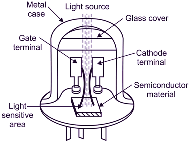
The Light-Activated SCR (LASCR) has a structure similar to that of a Silicon-Controlled Rectifier (SCR). It consists of three semiconductor regions: the P-type anode, the N-type cathode, and the N-type gate. However, LASCRs are designed with an additional light-sensitive layer integrated near the gate terminal. This layer allows the LASCR to be triggered into conduction by incident light.
Working Principle
The LASCR operates like a standard SCR with an optoelectronic twist.
In the absence of light, the LASCR remains in a non-conducting (OFF) state, similar to a regular SCR. However, when light of sufficient intensity strikes the light-sensitive layer near the gate terminal, it generates electron-hole pairs in the material. These charge carriers create a conducting path, forward-biasing the P1-N1 junction and initiating the conduction process. Once triggered, the LASCR remains conducting (ON) until the current falls below a certain level or the external circuit interrupts it.
Applications of LASCR
Light-activated SCR devices are employed in various optoelectronic applications, including:
- Light-activated switches: LASCRs can be used as light-activated switches in remote-control systems or other applications where light signals initiate the switching process.
- Optical sensing: LASCRs find use in optical sensors, where incident light triggers the device to detect light levels or variations.
- Fiber optic communication: LASCRs play a role in fiber optic communication systems, aiding in light modulation and signal detection.
Advantages and Limitations
Light-activated SCR devices offer several advantages, including:
- Non-electrical triggering: The ability to trigger LASCRs with light eliminates the need for complicated electrical control circuits.
- Fast response time: LASCRs have rapid response times, making them suitable for high-speed optoelectronic applications.
However, LASCRs also have certain limitations, such as:
- Limited sensitivity: LASCRs require a sufficient amount of incident light to trigger the device, which may limit their use in low-light environments.
- Narrow wavelength range: LASCRs are generally designed to respond to specific wavelengths of light, restricting their applicability to certain light sources.
Programmed Unijunction Transistor (PUT)
The Programmed Unijunction Transistor (PUT) is a specialized semiconductor device that belongs to the family of unijunction transistors. PUTs are widely used in timing, triggering, and relaxation oscillator circuits due to their unique characteristics and ease of use. In this section, we will explore the construction, working principle, and applications of Programmed junction transistors.
Construction of PUT
The Programmed junction transistor (PUT) consists of a single silicon semiconductor material with three terminals: the anode (A), the cathode (K), and the gate (G). It is designed with a P-type region and two N-type regions, with the gate terminal placed between the two N-regions.
Working Principle
The PUT operates based on the principles of negative resistance and the ability to control the triggering voltage. The device’s behavior is influenced by the gate voltage, making it unique among other types of transistors.
In the blocking state, the PUT remains non-conductive, with a high resistance between the anode and cathode. When a voltage is applied to the anode concerning the cathode, the voltage across the two N-regions becomes forward-biased. If the gate voltage is lower than a specific threshold (the “intrinsic standoff ratio”), the device remains in thblockingver, when the gate voltage exceeds the intrinsic standoff ratio, the PUT enters the negative resistance region, which triggers a rapid decrease in resistance between the anode and cathode. This results in a sharp increase in current flow through the device, known as the “negative resistance region.” Once triggered, the PUT stays conducting until the current drops below a specified holding current or until the external circuit interrupts it.
Applications of PUT
Programmed Unijunction Transistors have various applications, including:
Timing circuits: PUTs are widely used in timing circuits to generate precise and repetitive time intervals, such as in pulse generators or time-delay circuits.
Relaxation oscillators: PUTs can be utilized in relaxation oscillators, producing square or sawtooth waveforms for various electronic applications.
Triggering devices: PUTs serve as triggering devices in SCR (Silicon-Controlled Rectifier) and TRIAC (Triode for Alternating Current) circuits, controlling the firing of these devices.
Advantages and Limitations
Programmed Unijunction Transistors offer several advantages, including:
- Easy to use: PUTs have a straightforward operating principle and are easy to integrate into various circuit designs.
- Precise timing: PUTs provide accurate and repeatable timing intervals in timing and oscillator circuits.
However, PUTs also have some limitations, such as:
- Limited current handling capacity: PUTs are not suitable for high-current applications, as they typically have lower current ratings compared to other power devices.
- Temperature sensitivity: PUT characteristics may vary with temperature changes, requiring consideration in certain applications.
Conclusion
The blog post “Types of Thyristors” provides a comprehensive overview of various thyristor types and their applications. It introduces the basic working principles and construction of thyristors before delving into specific types like SCRs, GTOs, SCS, and TRIACs. Specialized thyristors such as RCTs, GATTs, MCTs, and LASCRs are also discussed. The post highlights the advantages, limitations, and key applications of each type, offering readers valuable insights to make informed decisions in selecting the appropriate thyristor for their projects. Overall, the blog post serves as a valuable guide, demonstrating the significance of thyristors in powering diverse electronic and power control systems across various industries.
FAQs about Types of Thyristors
1. What are thyristors?
Thyristors are semiconductor devices used in electronic circuits for power control and switching. They are capable of handling high currents and voltages, making them suitable for various applications.
2. What are the different types of thyristors?
There are several types of thyristors, including Silicon-Controlled Rectifiers (SCRs), Gate Turn-Off Thyristors (GTOs), Silicon-Controlled Switches (SCS), Triode for Alternating Current (TRIAC), Reverse Conducting Thyristors (RCTs), Gate Assisted Turn-Off Thyristors (GATTs), MOS-Triggered Thyristors (MCTs), and Light-Activated SCRs (LASCRs).
3. What are the advantages of TRIACs?
TRIACs offer bidirectional conduction, allowing them to control AC in both positive and negative half-cycles. They are commonly used in applications like light dimmers, motor speed control, and power switching.
4. What makes GTOs different from conventional thyristors?
Gate Turn-Off Thyristors (GTOs) can be turned off using a gate signal, unlike conventional thyristors that need a reduction in current. This feature enables faster switching and precise control, making GTOs suitable for high-power and high-frequency applications.
5. What are the applications of LASCRs?
Light-activated SCRs (LASCRs) are used in optoelectronic applications where they can be triggered into conduction by incident light. They find use in light-activated switches, optical sensors, and fiber optic communication systems.