Unlock a new level of efficiency with LinkSemi’s Excess Electronic Components Module, designed to streamline your inventory sales and minimize excess costs. We provide exceptional Cost Saving Opportunities in Electronic Components procurement through AI-driven insights and automated workflows. Additionally, our advanced Electronic Component Shortage Tool helps mitigate supply chain disruptions, ensuring smooth production and uninterrupted operational efficiency.
What is a Rectifier and Why is it Important?
A rectifier, in the simplest terms, is an electrical device that converts alternating current (AC), which periodically reverses direction, into direct current (DC) that flows consistently in one direction. The process of this conversion is aptly named ‘rectification’.
To visualize this, imagine ocean waves (representing AC) with their crest and trough, continuously rising and falling. A rectifier would then be akin to a mechanism that transforms these fluctuating waves into a calm, steady stream of water, similar to a tranquil river (representing DC).
The importance of rectification in electronics is paramount. Many electronic devices, from the smallest of personal gadgets to large industrial machinery, require a stable and consistent power supply to function efficiently and safely. AC, being variable, can pose challenges for devices that need a constant voltage or current. Here’s where the various types of rectifiers come into play. They act as gatekeepers, ensuring that our devices receive the kind of power they are designed for, thus prolonging their lifespan and ensuring optimal performance.
In addition to device protection and optimization, rectifiers play a significant role in power transmission. In large-scale scenarios, like national power grids, rectifiers are employed in converting high voltage AC into DC for more efficient and loss-minimized transmission over long distances. Once at the destination, the process is reversed to provide usable AC power to homes and businesses.
In essence, without the pivotal function of rectifiers, our modern electronic landscape would be vastly different, less efficient, and potentially fraught with challenges. As we delve deeper into the types of rectifiers in subsequent sections, you’ll come to appreciate the nuances and specialized applications of each.
Types of Bridge Rectifiers: 1. Half-Wave Rectifier
The half-wave rectifier, as its name suggests, is the most basic type of rectifier that allows only one half of an incoming AC wave to pass through, effectively eliminating the other half. It’s the foundational block from which more advanced types of rectifiers have evolved. Let’s break down its mechanism and nuances.
Working Principles of Half-Wave Rectifiers
A half-wave rectifier utilizes a single diode to process the incoming AC signal. When the AC voltage is positive (positive half-cycle), the diode becomes forward-biased and allows the current to flow through to the output. Conversely, during the negative half-cycle, the diode becomes reverse-biased, blocking the current and resulting in zero output. Thus, only half of the wave, specifically the positive half, is transferred to the output, while the negative half is completely removed.

Advantages and Disadvantages of Half-Wave Rectifiers
Pros:
- Simplicity: Its design is straightforward, making it easy to understand and implement.
- Low Cost: Due to the minimal components required.
Cons:
- Low Efficiency: Since only half of the input wave is utilized, it’s inherently less efficient than other rectifiers.
- Increased Ripple: The output isn’t as smooth as other types of rectifiers, leading to a “ripple” effect, which might require further filtering for some applications.
Applications of Half-Wave Rectifiers
While the half-wave rectifier’s efficiency might seem lacking, it finds its niche in specific applications where precision isn’t the prime concern, such as:
- Signal demodulation in radio receivers.
- Power supplies for some low-cost electronic devices where the ripple isn’t a significant concern.
In summary, the half-wave rectifier serves as an introduction to the realm of rectification. While its application might be limited in comparison to its more advanced counterparts, its fundamental principle forms the bedrock upon which other types of rectifiers are built.
Types of Bridge Rectifiers: 2. Full-Wave Rectifier
Progressing from the rudimentary half-wave rectification, the full-wave rectifier stands as a more evolved and efficient counterpart. As the nomenclature suggests, this rectifier effectively harnesses both the positive and negative half-cycles of the AC input, ensuring a more consistent and robust DC output.
Working Principles of Full-Wave Rectifiers
A full-wave rectifier processes both halves of an AC wave to produce a DC output. Unlike the half-wave rectifier, which discards the negative half-cycle, the full-wave version inverts the negative half-cycle to make it positive, thereby maximizing the use of the incoming AC signal.
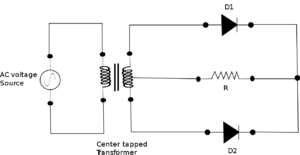
There are two prevalent configurations for full-wave rectification: the center-tapped and the bridge rectifier (to be discussed in the subsequent section). In the center-tapped design, two diodes are employed, with a center-tapped transformer splitting the AC input into two halves, allowing each diode to handle one half of the cycle.
Advantages and Disadvantages of Full-Wave Rectifiers
Pros:
- Enhanced Efficiency: Since it uses both halves of the AC wave, it’s inherently more efficient than the half-wave rectifier.
- Reduced Ripple: A smoother output due to the more frequent pulses of DC, which makes it easier to filter and stabilize.
Cons:
- Complexity: Requires more components, including the center-tapped transformer, making the design more intricate.
- Cost: Given the additional components, especially the transformer, it tends to be pricier than its half-wave counterpart.
Applications of Full-Wave Rectifiers
Owing to its superior efficiency and smoother output, the full-wave rectifier finds a broader array of applications, including:
- Power supplies for electronic devices, where a stable DC supply is imperative.
- Battery charging stations, requiring consistent DC input.
- In certain telecommunication devices, where signal integrity is paramount.
In the grand tapestry of rectification, the full-wave rectifier represents a midpoint—offering a balance between efficiency and complexity. It underscores the continuous quest in electronics for optimizing performance, even as we grapple with the trade-offs between simplicity and effectiveness.
Types of Bridge Rectifiers: 3. Bridge Rectifier
A bridge rectifier employs four diodes, arranged in a bridge configuration, to convert the entire AC input waveform (both positive and negative half-cycles) into a pulsating DC output. The brilliance of this design lies in its ability to use both half-cycles without the need for a center-tapped transformer.

Working Principle of Bridge Rectifiers
During the positive half-cycle of the AC input, two of the four diodes (diagonally opposite each other) become forward-biased, allowing current to flow through them, while the other two remain reverse-biased. During the negative half-cycle, the roles reverse, with the previously non-conducting diodes now facilitating the current flow, effectively inverting the negative half to a positive output.
Advantages and Disadvantages of Bridge Rectifiers
Pros:
- No Need for Center-Tap: The bridge rectifier eliminates the requirement of a center-tapped transformer, often leading to cost and space savings.
- Improved Reliability: With four diodes sharing the operational load, the design inherently offers enhanced reliability.
- High Peak Voltage: Offers higher peak voltage output compared to the center-tapped full-wave rectifier.
Cons:
- Voltage Loss: Due to two diodes being in series during each half-cycle, there’s a double voltage drop, which can reduce the overall efficiency slightly.
- Complexity: The increased number of diodes can make the circuit more intricate than a simple half-wave design.
Applications of Bridge Rectifiers
Given its practical benefits and efficient design, bridge rectifiers are ubiquitously employed across various applications, such as:
- Power supply units for a myriad of electronic devices, from computers to home appliances.
- Battery charging circuits requiring a consistent and robust DC source.
- In power conversion units like inverters and converters.
To learn more about bridge rectifiers and their details, see our guide on types of bridge rectifiers.
Comparison Table of Different Types of Rectifiers
In electronics, particularly when selecting components for specific applications, having a concise comparative summary is invaluable. Below is a comparison table that juxtaposes the three rectifier types discussed: Half-Wave, Full-Wave (Center-Tapped), and Bridge Rectifier. This table will aid in quickly discerning their characteristics, advantages, disadvantages, and ideal use cases.
| Parameter | Half-Wave Rectifier | Full-Wave Rectifier (Center-tapped) | Bridge Rectifier |
| Definition | Uses a single diode to allow only the positive half of the AC wave. | Uses two diodes with a center-tapped transformer to utilize both AC half-cycles. | Uses four diodes in a bridge configuration to harness both AC half-cycles. |
| Number of Diodes | 1 | 2 | 4 |
| Advantages | Simplicity, Low Cost | Enhanced Efficiency, Reduced Ripple | No Need for Center-Tap, High Peak Voltage, Improved Reliability |
| Disadvantages | Low Efficiency, Increased Ripple | Complexity, Cost | Voltage Loss, Complexity |
| Typical Efficiency | Low | Medium to High | High |
| Ripple Factor | High | Medium | Low to Medium |
| Voltage Drop | Single diode drop | Single diode drop per half-cycle | Double diode drop (2 in series per half-cycle) |
| Transformer Requirement | No | Center-tapped | No |
| Use Case | Signal demodulation, Low-cost power supplies | Electronic devices requiring stable DC, Battery charging | General-purpose power supplies, Inverters, Converters, High-demand applications |
This comparative table offers a snapshot of each rectifier’s features, guiding engineers and hobbyists alike in making informed choices based on their specific needs. It encapsulates the trade-offs and benefits, emphasizing that while there’s no one-size-fits-all in the world of rectifiers, understanding their nuances can lead to optimal solutions.
Conclusion
The realm of electronics is vast, intricate, and continually evolving, with rectifiers standing as a testament to the field’s foundational importance. As we’ve journeyed through the various types of rectifiers, it becomes palpable that each design, with its unique attributes and constraints, serves distinct needs in the electronic landscape.
Understanding the types of rectifiers is more than an academic endeavor—it’s a practical guide for anyone seeking to harness the transformative power of electricity. From the elementary half-wave rectifier, offering simplicity at the expense of efficiency, to the full-wave and bridge rectifiers, balancing complexity with performance, the choices are as varied as the applications they serve.
In a world increasingly reliant on electronic devices, from the tiny circuits in our smartwatches to the expansive grids powering our cities, the knowledge of rectifiers becomes ever more pertinent. While the types of rectifiers may seem like mere components on a circuit board, they underscore the broader narrative of electronics: a tale of innovation, optimization, and the perpetual quest to improve.
FAQ
- What are the primary types of rectifiers covered in this blog post?
The blog delves into three fundamental types of rectifiers: Half-Wave, Full-Wave (Center-tapped), and Bridge Rectifier.
- Why is it crucial to understand different types of rectifiers in electronics?
Recognizing the types of rectifiers aids in selecting the appropriate component for efficient AC-to-DC conversion, tailored to specific applications and requirements.
- How does the efficiency of a bridge rectifier compare to other types of rectifiers?
The bridge rectifier offers high efficiency as it uses both AC half-cycles without a center tap, making it a robust choice for many applications.
- Are there modern advancements in rectification beyond the types of rectifiers discussed?
While the blog focuses on three primary rectifiers, the electronics field continually evolves, bringing forth innovations and optimizations in rectification techniques.