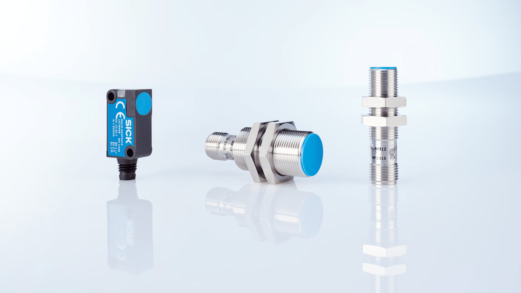
Magnetic sensors, often overlooked yet integral components, have revolutionized Sensors and Measurement systems in contemporary technology. These devices act as the perceptive organs of numerous systems, allowing them to detect and respond to magnetic field variations in their environment. Whether through Hall effect sensors measuring magnetic flux density or magnetoresistive sensors gauging changes in electrical resistance, magnetic sensors are crucial for maintaining precise control and accurate measurements across a wide range of applications. They also complement Types of Optical Sensors and Types of Electrical Meters, enhancing system reliability and performance.
The progression of magnetic sensor technology, alongside advancements in Types of Temperature Sensors and Types of Switches, has been a pivotal milestone in engineering, driving the sophisticated monitoring systems we rely on today. Magnetic sensors profoundly impact fields from automotive engineering to consumer electronics by facilitating more efficient and high-performance processes. Whether in smartphone compasses, industrial motor controls, or automotive safety systems, magnetic sensors in various forms are indispensable for measuring and regulating magnetic fields.
Magnetic sensors enable precise position and speed detection, improve energy efficiency in motors, enhance vehicle safety, and increase overall system reliability. Along with Types of Optical Sensors and Types of Temperature Sensors, magnetic sensors offer benefits such as:
- Accurate real-time magnetic field measurements across a wide range of intensities.
- Non-contact sensing, reducing wear in mechanical systems.
- Contributions to energy conservation by optimizing motor control and power management.
- Enhanced safety by monitoring critical parameters in automotive and industrial settings.
Magnetic sensors have become ubiquitous across industries, from automotive and consumer electronics to industrial automation and aerospace. They, along with Types of Optical Sensors and Types of Temperature Sensors, advance technologies like electric vehicles, renewable energy systems, and medical imaging.
The world of magnetic sensors is diverse, including Hall effect, magnetoresistive, fluxgate, and SQUID (Superconducting Quantum Interference Device) sensors. This diversity enables precise magnetic field measurement across a wide range of applications, from Earth’s magnetic field detection to high-intensity field measurements in scientific research.
As technology evolves, magnetic sensing promises greater sensitivity, miniaturization, and integration. Understanding the various types of magnetic sensors, alongside crucial categories like Types of Optical Sensors and Types of Temperature Sensors, is essential for anyone involved in magnetic field detection, driving innovative solutions to magnetically related challenges.
Different Types of Magnetic Sensors
The world of magnetic sensors is diverse, with various types designed to measure specific magnetic field strengths, operate in particular environments, or suit specific applications. Understanding these different types is crucial for engineers, technicians, and anyone involved in magnetic field measurement and control. Here are the main types of magnetic sensors:
- Hall Effect Sensors
- Magnetoresistive Sensors
- Fluxgate Sensors
- Induction Coil Sensors
- Search Coil Magnetometers
- SQUID (Superconducting Quantum Interference Device) Sensors
- Optical Pumping Magnetometers
- Reed Switches
Each of these magnetic sensor types has its own set of characteristics, advantages, and limitations, making them suitable for different applications across various industries. The choice of magnetic sensor depends on factors such as the required sensitivity, magnetic field strength range, frequency response, environmental conditions, and cost considerations.
Understanding the distinctions between these sensor types is essential for optimizing system performance and cost-effectiveness. For instance, Hall Effect sensors are widely used in automotive and consumer electronics due to their robustness and compact size. Magnetoresistive sensors offer higher sensitivity and are often used in navigation and position sensing. Induction coil sensors and search coil magnetometers excel in measuring changing magnetic fields and are often used in geophysical surveys and electromagnetic compatibility testing. Fluxgate sensors provide high accuracy for measuring DC and low-frequency AC fields. SQUID sensors offer extremely high sensitivity for specialized applications, while reed switches provide simple and reliable magnetic field detection for proximity sensing.
As the field of magnetic sensing continues to evolve, we’re seeing increasing integration of multiple sensor types within single devices, as well as the development of novel sensing principles. This trend towards hybrid and innovative sensing solutions is opening up new possibilities for magnetic field detection and measurement across an unprecedented range of applications and industries.
Types of Magnetic Sensor Specifications in Table
| Sensor Type | Key Features | Types | Common Applications | Advantages | Disadvantages | Relative Cost |
| Hall Effect Sensors | Detect magnetic flux density; output proportional to field strength | 1. Linear (Analog) Output
2. Digital Output (Bipolar, Unipolar) |
– Automotive systems- Industrial automation
Consumer electronics Current sensing |
– Low signal error
-Environmental resistance – Fast response time – Non-contact operation |
– Magnetic field interference
– Temperature sensitivity – Limited load switching |
Low to Moderate |
| Magnetoresistive Sensors | Change resistance in presence of magnetic field | 1. High Field Sensors
2. Low Field Sensors |
– Path and angle measurement
– Current measurement – Wheel speed sensors – Metal detection |
– Extremely precise
– Very small size – Energy-efficient – High sensitivity |
– Sensitivity to interfering fields
– Temperature drift – Limited linear range |
Moderate |
| Fluxgate Sensors | Use magnetic saturation principle | 1. Standard Fluxgate
2. C-type Fluxgate 3. IT-type Fluxgate 4. Low-frequency Fluxgate |
– Geophysical surveys
– Space exploration – Navigation systems – Current measurement |
– High precision and sensitivity
– Wide measurement range – Low power consumption – Excellent accuracy |
– Limited bandwidth (simple designs
– Large noise at excitation frequency – Complex design |
Moderate to High |
| Induction Coil Sensors | Generate signal from changing magnetic fields | 1. Air Core Sensors
2. Ferromagnetic Core Sensors 3. Rogowski Coil 4. Gradiometer Sensors |
– Geophysical surveys
– Metal detection – Space exploration – Industrial sensing |
– Simple construction
– Wide frequency range – High sensitivity – No power supply required |
– Output depends on rate of change
– EMI sensitivity – Difficulty with very low frequencies |
Low to Moderate |
| Search Coil Magnetometers | Measure varying magnetic fields | 1. Air-core Magnetometers
2. Ferromagnetic-core Magnetometers 3. Dual-band Magnetometers 4. Three-axis Magnetometers |
– Space research
– Geophysical surveys – Magnetotellurics – Eye tracking |
– High sensitivity
– Wide frequency range – Vector measurements – Robust design |
– Limited to AC measurements
– Frequency-dependent sensitivity – Size constraints for low frequencies |
Moderate |
| SQUID Sensors | Use superconducting loops with Josephson junctions | 1. DC SQUID
2. RF SQUID 3. Nano-SQUID 4. High-Temperature SQUID |
– Biomagnetism (MEG, MCG
– Materials science – Quantum computing – Fundamental physics |
– Extreme sensitivity
– Low noise levels – Wide dynamic range – High temporal resolution |
– Cryogenic cooling required
– Complex operation – High cost – Size limitations |
Very High |
| Optical Pumping Magnetometers | Use quantum properties of alkali metal vapors | 1. Spin-Exchange Relaxation-Free (SERF
2. Mx Magnetometers 3. Bell-Bloom Magnetometers 4. Cesium Vapor Magnetometers |
– Magnetoencephalography
– Geophysical surveys – Space exploration – Medical diagnostics |
– Extremely high sensitivity
– Room temperature operation – Compact and potentially wearable< – Vector field measurements |
– Orientation sensitivity
– Environmental sensitivity – Power consumption – Complexity |
High |
| Reed Switches | Ferromagnetic reeds in sealed glass envelope | 1. Normally Open (NO)
2. Normally Closed (NC) 3. Change-over (SPDT) 4. Mercury-wetted 5. High-voltage 6. Miniature and Micro |
– Security systems
– Automotive industry – Consumer electronics – Industrial equipment |
– Long operational lifespan
– Hermetically sealed – Low power consumption – Simple operation |
– Limited current handling
– Fragility -Sensitivity to strong magnetic fields – Contact wear |
Low |
What are Hall Effect Sensors?
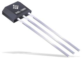
Hall effect sensors are electronic devices that detect and measure magnetic fields using the Hall effect, a principle discovered by Edwin Hall in 1879. These sensors convert magnetic field information into electrical signals, making them valuable in various applications across industries. Hall effect sensors are widely used, with hundreds of millions of integrated circuits (ICs) sold annually by approximately 50 manufacturers, contributing to a global market of around one billion dollars. At their core, Hall effect sensors consist of a thin strip of semiconductor material, typically silicon, through which an electric current flows continuously. This arrangement creates a baseline magnetic field within the sensor. When an external magnetic field is introduced, it interacts with the sensor’s internal field, causing a measurable change in the voltage across the semiconductor strip. This voltage change, known as the Hall voltage, is directly proportional to the strength of the external magnetic field, allowing the sensor to precisely detect and quantify magnetic fields in its vicinity.
Working Principle of Hall Effect Sensors
The Hall effect sensor’s operation is based on the interaction between electric current and magnetic fields. A fixed DC bias current is applied along one axis across a thin strip of metal or semiconductor material called the Hall element transducer. When exposed to a magnetic field perpendicular to the current flow, charge carriers in the material are deflected by the Lorentz force. This deflection creates a potential difference (Hall voltage) across the Hall element, measured by sensing electrodes placed on opposite sides of the element along another axis. The Hall voltage produced is proportional to the strength of the magnetic field component perpendicular to both the current flow and the sensing electrodes. This relationship allows the sensor to accurately measure the intensity of the magnetic field. Hall effect sensors can detect both static and changing magnetic fields, unlike inductive sensors that only respond to field changes. The output signal from a Hall effect sensor represents the density of the magnetic field around the device, and when this density exceeds a preset threshold, the sensor generates the Hall voltage output.
Applications of Hall Effect Sensors
Hall effect sensors find applications in numerous fields, including:
- Automotive systems: Speed sensors, anti-lock braking systems (ABS), and ignition timing in internal combustion engines.
- Industrial automation: Proximity sensing, positioning, and speed detection.
- Consumer electronics: Smartphones, GPS devices, and electric airsoft guns.
- Medical devices: Various sensing applications.
- Fluid flow sensors and pressure sensors.
- Current sensing in electrical systems.
These sensors are often used as robust, contactless alternatives to mechanical switches or potentiometers.
Types of Hall Effect Sensors
- Linear (Analog) Output Sensors: These sensors provide a continuous voltage output proportional to the magnetic field strength. They are used in applications requiring precise field measurements, such as current sensing and position detection in automotive systems.
- Digital Output Sensors: These sensors produce a binary (on/off) output based on magnetic field strength, using a Schmitt trigger circuit. They come in two subtypes:
Bipolar Sensors: Require both positive and negative magnetic fields to operate. Used in rotary encoders and speed sensors.
b. Unipolar Sensors: Operate with a single magnetic pole, typically the South pole. Common in simple on/off applications like door sensors and lid detectors.
Advantages of Hall Effect Sensors
- Low Signal Error: Output errors as low as 1%, ensuring high reliability and accuracy.
- Environmental Resistance: When properly designed, they can operate in wet or dusty environments.
- Affordability: Offer good value for their cost, depending on the specific variant.
- Fast Response Time: Can track current changes and waveforms almost instantaneously.
- Longevity: Durable and can last a very long time with proper installation.
- Versatility: Can measure low and high currents, various frequencies, and even zero speed.
- Non-Contact Operation: No wear from friction, enhancing durability.
Disadvantages of Hall Effect Sensors
- Magnetic Field Interference: External magnetic fields can disturb measurements, especially for sensors with low output limits (20mA or less).
- Temperature Sensitivity: Extreme temperature variations can affect accuracy.
- Limited Load Switching: Many digital Hall effect sensors have small output drive capabilities and may require additional components for switching large electrical loads.
In conclusion, Hall effect sensors are versatile and reliable devices used across various industries for detecting and measuring magnetic fields. Their non-contact operation, longevity, and ability to work in challenging environments make them valuable in many applications. However, considerations such as magnetic interference and temperature sensitivity should be taken into account when implementing these sensors in specific applications.
What are Magnetoresistive Sensors?
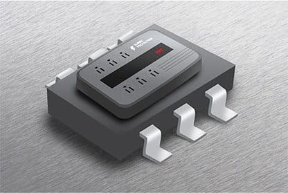
Magnetoresistive sensors are sophisticated devices that detect and measure magnetic fields by utilizing the magnetoresistive effect. This effect causes the electrical resistance of a ferromagnetic thin film alloy, typically made of mixed alloys such as iron and nickel, to change in the presence of an external magnetic field. Unlike many sensors that directly measure physical properties, magnetoresistive sensors detect changes in magnetic fields, which can carry information on properties such as direction, presence, rotation, angle, or electrical currents. These sensors are exceptionally small, robust, and energy-efficient, making them ideal for applications where continuous energy supply is not available. They often employ a Wheatstone bridge configuration to maximize sensitivity and minimize temperature influences. The construction typically includes a magnetic preferred direction in the horizontal axis, known as magnetic anisotropy, which helps maintain measurement stability even when exposed to external magnetic fields.
Working Principle of Magnetoresistive Sensors
The operation of magnetoresistive sensors is primarily based on the anisotropic magnetoresistive (AMR) effect. In this phenomenon, the electrical resistance of the sensor material depends on the angle between the current direction and the magnetization vector, which can be influenced by an external magnetic field. The resistance is lowest when the angle is 90 degrees and highest when the current flows parallel to the magnetization. When an object with its own magnetic field approaches the sensor, it changes the electrical resistance of the sensor material. This change allows the sensor to detect the angle and distance of the external magnetic field relative to the sensor. The sensor’s ferromagnetic material is typically designed with a magnetic preferred direction in the horizontal axis, known as magnetic anisotropy, which helps maintain measurement stability.
Applications of Magnetoresistive Sensors
Magnetoresistive sensors find applications in various fields, including:
- Path and angle measurement
- Determination of magnetic fields
- Highly dynamic current measurement
- Contactless switches
- Dynamic measurements under extreme conditions (e.g., in vehicle engines)
- Wheel speed sensors in automotive systems
- Earth magnetic field detection for compass and navigation applications
- Metal detection
- Linear displacement measurement
Types of Magnetoresistive Sensors
- High Field Sensors: These sensors operate in strong magnetic fields where the field strength is sufficient to saturate the soft magnetic sensor material (roughly for H>10 kA/m). They are commonly used in contactless angular sensors, such as the KMT32B, KMT36H, and MLS-position sensors.
- Low Field Sensors: In these sensors, the magnetization vector is mainly determined by the form of the sensor strips. The external field causes a twist in the magnetization, changing the resistance due to the MR effect. Examples include linear low field sensors like the MR174B die and KMY sensors, and switching sensors like the MS32.
Advantages of Magnetoresistive Sensors
- Extremely precise measurements
- Robust construction
- Very small size
- Energy-efficient operation
- Wide range of applications
- Suitable for extreme environments
- Non-contact operation, resulting in no wear and friction
- High reliability
- Low and stable offset
- High sensitivity, capable of measuring weak magnetic fields
- Wide operating frequency range (0 Hz to 1 MHz)
- Ability to measure zero speed
- Fast response time
Disadvantages of Magnetoresistive Sensors
- Sensitivity to interfering magnetic fields
- Potential damage from very strong magnetic fields
- Temperature drift
- Limited linear range
- Poor temperature characteristics
- Complicated setup process
What are Fluxgate Sensors?
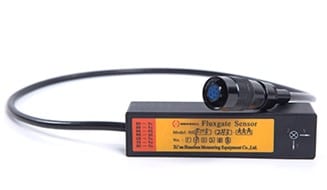
Fluxgate sensors are sophisticated devices used for measuring magnetic fields. They consist of a ring core made of a highly magnetically permeable alloy, typically wrapped with two coil windings: the drive winding and the sense winding. Some sensors may also include a third feedback winding for closed-loop operation. These sensors are known for their high precision and ability to measure subtle changes in magnetic fields.
Working Principle of Fluxgate Sensors
Fluxgate sensors operate on the principle of magnetic saturation. The ring core can be conceptualized as two separate half cores. As current flows through the drive winding, one half core generates a field component in the same direction as the external field (Hext), while the other generates a field component in the opposite direction. This arrangement allows the sensor to detect and measure changes in the external magnetic field with high sensitivity.
Applications of Fluxgate Sensors
Fluxgate sensors find applications in various fields, particularly where precise magnetic field measurements are required. While specific applications weren’t provided in the given information, these sensors are commonly used in:
- Geophysical surveys
- Space exploration
- Navigation systems
- Current measurement in power systems
- Non-destructive testing
Types of Fluxgate Sensors
- Standard Fluxgate Sensor: Similar to a closed-loop Hall effect design. This type uses a main toroidal core for field sensing, which can be subject to magnetic offset. Despite this limitation, standard fluxgate sensors are widely used due to their balance of performance and cost-effectiveness in many applications.
- C-type Fluxgate: Offers improved performance by:
- Using the entire toroidal core as the field sensing element, without a gap
- Ensuring high-frequency performance with a separate core for the transformer effect
- IT-type Fluxgate: Further improves performance by:
- Duplicating the field sensing element, using two toroidal cores with opposing excitation coils
- Enhancing the design of the high-frequency current transformer and processing electronics
- Low-frequency Fluxgate: A cost-effective version using only the low-frequency part of the C-type Fluxgate sensor, without the current transformer.
Advantages of Fluxgate Sensors
- High precision and sensitivity
- Fast response time
- Wide measurement range (from weak to strong magnetic fields)
- Low power consumption
- Low offset and offset drift
- Excellent accuracy, especially for small current measurements
- Excellent over-current recovery
- Large dynamic range
- Very high resolution
- Suitable for broad operating temperature ranges
- High bandwidth and fast response time (especially in C-type and IT-type)
Disadvantages of Fluxgate Sensors
- Limited bandwidth for simpler designs
- Large noise level at the excitation frequency
- Potential voltage noise injection into primary lines
- Relatively high secondary power consumption
- Complex design, making customization more difficult
- More expensive to produce due to complex designs
What are Induction Coil Sensors?
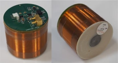
Induction coil sensors, also known as search coils, pickup coils, or magnetic loop sensors, are devices used to detect and measure magnetic fields. They consist of a coil of wire, often wrapped around a core material, which generates an electrical signal in response to changes in the surrounding magnetic field. These sensors can be designed with air cores or ferromagnetic cores, depending on the specific application requirements.
Working Principle of Induction Coil Sensors
Induction coil sensors operate based on Faraday’s law of electromagnetic induction. When a changing magnetic field passes through the coil, it induces an electromotive force (EMF) in the wire. The output signal of the sensor is proportional to the rate of change of the magnetic flux density (dB/dt). To obtain a measurement proportional to the flux density (B) itself, integration of the output signal is often necessary. The sensitivity of the sensor can be improved by increasing the number of turns in the coil and the active area of the sensor. For sensors with ferromagnetic cores, the core material increases the magnetic flux, thereby enhancing sensitivity and allowing for reduced sensor dimensions.
Applications of Induction Coil Sensors
Induction coil sensors find applications in various fields, including:
- Geophysical surveys
- Electromagnetic field measurements
- Metal detection
- Magnetic anomaly detection
- Space exploration
- Industrial sensing and control systems
- Borehole transmitters for petroleum reservoir monitoring
Types of Induction Coil Sensors
- Air Core Sensors: Simple and low-cost, suitable for a wide range of frequencies. These sensors consist of a coil wound around a non-magnetic core, typically air. They offer good linearity and are less susceptible to core saturation issues compared to ferromagnetic core sensors.
- Ferromagnetic Core Sensors: Offer increased sensitivity and reduced size compared to air core sensors. The ferromagnetic core concentrates the magnetic flux, enhancing the sensor’s response. However, care must be taken to avoid core saturation at high field strengths, which can lead to non-linear behavior.
- Rogowski Coil: A special type of air-core coil used for measuring alternating currents. It is designed as a toroidal coil without an iron core, which allows it to measure high-frequency currents without saturation effects. Rogowski coils are particularly useful for measuring large currents in power systems and for current pulse measurements.
- Gradiometer Sensors: Used for measuring magnetic field gradients. These sensors typically consist of two or more coils arranged to detect the spatial variation of the magnetic field. Gradiometers are effective at rejecting common-mode noise and are often used in geophysical surveys and biomagnetic measurements.
- Vibrating Coil Sensors: Employ mechanical vibration to modulate the magnetic field. By vibrating the coil at a known frequency, these sensors can detect DC or very low-frequency magnetic fields that would be difficult to measure with static coils. This technique can improve sensitivity and reduce low-frequency noise.
- Tangential Field Sensors: Designed to measure magnetic fields parallel to a surface. These sensors are particularly useful in non-destructive testing applications, such as detecting surface defects in metallic materials. Their design allows for high spatial resolution in measuring field components along a surface.
- Needle Probes: Small, precise sensors for localized measurements. These miniature sensors can be inserted into narrow spaces or used for point measurements with high spatial resolution. They are often employed in medical applications or for mapping magnetic fields in confined spaces.
Advantages of Induction Coil Sensors
- Simple construction and low-cost manufacturing
- Can be easily customized or built by users
- Wide frequency range capability
- High sensitivity, especially with ferromagnetic cores
- No power supply required for passive sensors
- Suitable for measuring large stray magnetic fields
- Can be designed for specific frequency ranges
Disadvantages of Induction Coil Sensors
- Output signal depends on the rate of change of flux density, requiring integration for B-field measurements
- Sensitivity to electromagnetic interference
- Difficulty in constructing sensors sensitive to very low frequencies (below 1 Hz)
- May require careful amplifier selection for low-frequency applications
- Ferromagnetic core sensors can introduce non-linearity due to core saturation
- Size constraints for low-frequency applications, as sensitivity often requires larger coils
What are Search Coil Magnetometers?
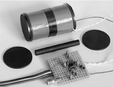
Search Coil Magnetometers, also known as induction magnetometers, are devices used to measure varying magnetic fields. They consist of a coil of wire, often wrapped around a high-permeability core, which generates an electrical signal in response to changes in the surrounding magnetic field. These instruments are particularly useful for measuring low-frequency electromagnetic waves and are commonly used in space physics and geophysical research.
Working Principle of Search Coil Magnetometers
Search Coil Magnetometers operate based on Faraday’s law of electromagnet
ic induction. When a changing magnetic field passes through the coil, it induces a voltage in the wire. The induced voltage (V) is proportional to the rate of change of the magnetic flux (dΦ/dt) and the number of turns (N) in the coil:
V = -N * dΦ/dt
The sensitivity of the sensor can be enhanced by increasing the number of turns in the coil, expanding the coil’s surface area, and employing a ferromagnetic core to concentrate the magnetic flux. The output of the coil is typically connected to a low-noise preamplifier, which amplifies and conditions the signal for further processing or transmission to the main electronics.
Applications of Search Coil Magnetometers
- Space research: Studying magnetic fields and plasma waves in space environments
- Geophysical surveys: Investigating Earth’s magnetic field variations
- Magnetotellurics: Exploring subsurface structures using natural electromagnetic fields
- Eye tracking: Measuring eye movement using coils embedded in contact lenses
- Non-destructive testing: Detecting flaws in metallic materials
- Education: Demonstrating principles of electromagnetism
- Natural electromagnetic wave observations on Earth
Types of Search Coil Magnetometers
- Air-core Magnetometers: Use coils wound around a non-magnetic core, typically air. They offer good linearity and are less susceptible to core saturation issues.
- Ferromagnetic-core Magnetometers: Utilize a high-permeability core to enhance sensitivity. These can achieve higher sensitivities but may be prone to core saturation at high field strengths.
- Dual-band Magnetometers: Employ two coils to extend the frequency range of measurement. Advanced designs like the “mutual reducer” can further extend the bandwidth beyond the resonance of the first coil.
- Three-axis Magnetometers: Consist of three orthogonal sensors to measure all components of the magnetic field vector simultaneously.
Advantages of Search Coil Magnetometers
- High sensitivity: Can measure very weak magnetic fields (down to a few tens of fT/√Hz at kHz frequencies)
- Wide frequency range: Capable of measuring from mHz up to hundreds of MHz
- Vector measurements: Can measure one or more components of the magnetic field
- Robust design: Suitable for harsh environments, including space applications
- No power required for the sensing element: The coil itself is a passive component
- Relatively small size and low power consumption for spaceflight applications
- Good for studying time-varying magnetic fields and waves
Disadvantages of Search Coil Magnetometers
- Limited to AC measurements: Cannot measure static (DC) magnetic fields
- Frequency-dependent sensitivity: Less sensitive at very low frequencies
- Size constraints: Lower frequencies often require larger coils, which can be a limitation in some applications
- Potential for core saturation: In ferromagnetic-core designs, strong fields can lead to non-linear behavior
- Susceptibility to electromagnetic interference: Proper shielding may be necessary
- Resonance issues: The coil’s natural resonance can limit the usable frequency range, though this can be mitigated with feedback techniques
- Complexity in multi-axis measurements: Achieving orthogonality in three-axis systems can be challenging
What are SQUID (Superconducting Quantum Interference Device) Sensors?
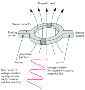
SQUID (Superconducting Quantum Interference Device) sensors are extremely sensitive magnetometers used to measure incredibly weak magnetic fields. These devices are based on superconducting loops containing Josephson junctions, which are thin insulating barriers between two superconductors. SQUIDs operate using quantum mechanical principles and can detect magnetic fields as low as 5×10⁻¹⁴ T (tesla) with a few days of averaged measurements, making them among the most sensitive magnetic field detectors available.
Working Principle of SQUID (Superconducting Quantum Interference Device)
Sensors SQUIDs operate based on two quantum phenomena: flux quantization in a closed superconducting loop and the Josephson effect. The key components are:
- Superconducting loop: Creates a path for supercurrent
- Josephson junctions: Act as weak links in the superconducting loop
When an external magnetic field is applied, it induces a screening current in the superconducting loop. This current generates an additional magnetic flux, which affects the phase difference across the Josephson junctions. The resulting voltage across the SQUID is highly sensitive to changes in the external magnetic field, allowing for extremely precise measurements.
The SQUID’s response is periodic with respect to the applied magnetic flux, with a period equal to the magnetic flux quantum (Φ0 = h/2e, where h is Planck’s constant and e is the elementary charge).
Applications of SQUID (Superconducting Quantum Interference Device) Sensors
- Biomagnetism: Magnetoencephalography (MEG) and magnetocardiography (MCG)
- Geophysics: Oil and mineral prospecting, earthquake prediction, and geothermal energy surveying
- Materials science: Magnetic property measurement systems (MPMS)
- Medical imaging: Low-field magnetic resonance imaging (MRI)
- Quantum computing: As sensors in quantum computers (e.g., D-Wave Systems)
- Fundamental physics: Detection of gravitational waves and tests of general relativity
- Non-destructive testing: Evaluation of materials and structures
- Nanoscale magnetometry: Characterization of magnetic nanoparticles and single-molecule magnets
Types of SQUID (Superconducting Quantum Interference Device) Sensors
- DC SQUID: Utilizes two Josephson junctions in parallel in a superconducting loop. It is highly sensitive, detecting changes in magnetic flux on the order of 10^-6 Φ0/√Hz, making it ideal for high-precision scientific applications despite its manufacturing complexity.
- RF SQUID: Features a single Josephson junction and is less sensitive than DC SQUIDs but cheaper and easier to produce. It operates based on the AC Josephson effect, often used in biomagnetism research where cost-effectiveness is prioritized over ultimate sensitivity.
- Nano-SQUID: A miniaturized version with a loop diameter of 100-200 nm, designed for measuring the magnetic responses of nanostructures and individual molecules. It excels in applications requiring high spatial resolution, such as quantum computing and molecular magnetism.
- High-Temperature SQUID: Made from high-temperature superconductors like YBCO, it operates at liquid nitrogen temperature (77 K), reducing costs and complexity. Though slightly less sensitive, it has practical uses in medicine, geophysics, and non-destructive testing.
Advantages of SQUID (Superconducting Quantum Interference Device) Sensors
- Extreme sensitivity: Can measure magnetic fields as low as 5×10⁻¹⁴ T with averaged measurements
- Low noise levels: As low as 3 fT·Hz−1⁄2
- Wide dynamic range: Can measure from very weak to relatively strong magnetic fields
- Vector measurements: Capable of measuring both magnitude and direction of magnetic fields
- High temporal resolution: Can operate at acquisition rates much higher than the frequencies of interest in many applications
- Versatility: Applicable in various fields from fundamental physics to medical imaging
Disadvantages of SQUID (Superconducting Quantum Interference Device) Sensors
- Cryogenic cooling requirement: Most SQUIDs need to operate at very low temperatures, typically using liquid helium (4.2 K) or liquid nitrogen (77 K for high-temperature superconductors)
- Complexity: Requires sophisticated electronics for operation and signal processing
- Sensitivity to external interference: Highly susceptible to external magnetic fields, requiring careful shielding
- Cost: Due to the need for cryogenic cooling and specialized materials, SQUID systems can be expensive
- Size limitations: The need for cooling systems can make SQUID-based instruments bulky
- Maintenance: Regular replenishment of cryogenic liquids is necessary
- Expertise required: Operation and data interpretation often require specialized knowledge
Despite these limitations, SQUIDs remain unparalleled in their ability to measure extremely weak magnetic fields, making them invaluable tools in various scientific and technological applications.
What are Optical Pumping Magnetometers?
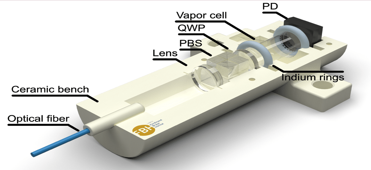
Optical Pumping Magnetometers (OPMs), or atomic magnetometers, are advanced quantum sensors designed to measure extremely weak magnetic fields with exceptional sensitivity. These devices use the quantum properties of alkali metal vapors, such as cesium, potassium, or rubidium, in a small glass cell. By interacting these alkali atoms with external magnetic fields and controlled laser light, OPMs can detect magnetic fields in the femtotesla (fT) range, about a billion times weaker than Earth’s magnetic field. Unlike superconducting quantum interference devices (SQUIDs), OPMs operate at room temperature, removing the need for cryogenic cooling. This makes them compact, potentially wearable, and versatile for applications ranging from biomagnetic measurements to geophysical surveys. Their high sensitivity, room-temperature operation, and vector field measurement capabilities position OPMs at the forefront of magnetic sensing technology, with applications in neuroscience, medical diagnostics, and fundamental physics research.
Working Principle of Optical Pumping Magnetometers
The working principle of Optical Pumping Magnetometers involves optical pumping and probing. First, a circularly polarized laser beam, tuned to a specific atomic transition of the alkali metal, creates a non-equilibrium distribution of atomic spin states, aligning the magnetic moments of the atoms and creating macroscopic magnetization in the vapor cell. In the presence of an external magnetic field, these aligned spins precess around the field direction at the Larmor frequency, proportional to the field strength. The second step involves probing this precession with a second laser beam (or the same beam in a different configuration) that passes through the vapor cell. The precessing spins cause a rotation in the probe beam’s polarization, known as Faraday rotation. Measuring this rotation with a photodetector and lock-in amplifier determines the Larmor frequency, and thus the external magnetic field strength, with extreme precision. This continuous process allows for real-time, highly sensitive magnetic field measurements.
Applications of Optical Pumping Magnetometers
- Magnetoencephalography (MEG): Brain activity mapping
- Magnetocardiography (MCG): Heart magnetic field measurements
- Geophysical surveys: Mineral exploration and archaeological studies
- Space exploration: Measuring planetary magnetic fields
- Fundamental physics research: Searching for axion-like dark matter
- Military and defense: Submarine detection and navigation
- Medical diagnostics: Non-invasive physiological measurements
- Materials science: Characterization of magnetic properties
Types of Optical Pumping Magnetometers
- Spin-Exchange Relaxation-Free (SERF) Magnetometers: Operate in ultra-low magnetic fields (below 10 nT) and achieve the highest sensitivities. They are ideal for applications like MEG and fundamental physics research. SERF magnetometers work by suppressing spin-exchange relaxation, which typically limits sensitivity in other OPM designs.
- Mx Magnetometers: Use radio-frequency (RF) fields to modulate the atomic spins. These are suitable for measuring Earth-strength magnetic fields (~50 μT) and are often used in geophysical applications. Mx magnetometers offer good sensitivity and can operate in a wide range of field strengths.
- Bell-Bloom Magnetometers: Employ amplitude-modulated pump light instead of RF fields. They can achieve high sensitivity and are less susceptible to RF interference, making them useful in electromagnetically noisy environments.
- Cesium Vapor Magnetometers: Specifically use cesium atoms as the sensing element. These are known for their high accuracy and stability, making them popular in geophysical surveys and space applications.
- Potassium Magnetometers: Use potassium vapor and are noted for their high sensitivity and low noise. They are particularly useful in applications requiring rapid measurements, such as airborne geophysical surveys.
Advantages of Optical Pumping Magnetometers
- Extremely high sensitivity: Can detect magnetic fields in the femtotesla range
- No cryogenic cooling required: Can operate at room temperature
- Compact and potentially wearable: Allows for flexible placement and mobile applications
- Vector field measurements: Can measure both magnitude and direction of magnetic fields
- Wide dynamic range: Can measure from very weak to Earth-strength magnetic fields
- Rapid readings: Provide fast measurement rates compared to some other magnetometer types
- Non-invasive: Ideal for biomedical applications
- Scalability: Can be miniaturized for dense sensor arrays
Disadvantages of Optical Pumping Magnetometers
- Orientation sensitivity: Performance can be affected by the sensor’s orientation relative to the magnetic field
- Environmental sensitivity: Require careful shielding from external magnetic interference
- Power consumption: Laser operation can require significant power, especially for portable devices
- Complexity: Require sophisticated optical and electronic components
- Cost: Can be more expensive than some other magnetometer types
- Warm-up time: May require time to stabilize for optimal performance
- Limited high-field performance: Some types (e.g., SERF) only work in low magnetic fields
- Cross-talk: In dense arrays, sensors can interfere with each other, requiring careful design
Despite these limitations, OPMs represent a significant advancement in magnetic field sensing technology, offering unparalleled sensitivity and versatility across a wide range of applications.
What are Reed Switches?
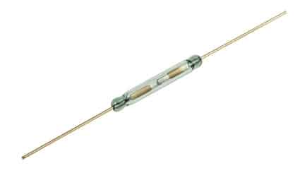
Reed switches are specialized electromechanical devices that operate using magnetic fields. Invented in 1936 by Walter B. Elwood at Bell Laboratories, these switches consist of two or three ferromagnetic metal reeds hermetically sealed within a glass envelope. The most common type features two flexible metal contacts that are normally open but close when exposed to a magnetic field. The term “reed” refers to the thin, flexible metal strips inside the switch, which resemble the vibrating reed in musical instruments. These reeds are typically made from a ferromagnetic material, often an alloy of nickel and iron. The glass envelope that houses the reeds is usually filled with an inert gas, such as nitrogen, to prevent oxidation and ensure a long operational life. This sealed construction makes reed switches suitable for use in various environments, including those with dust, moisture, or potentially explosive atmospheres.
Working Principle of Reed Switches
The operation of a reed switch is based on the interaction between the ferromagnetic reeds and an external magnetic field. In their resting state, the reeds are slightly separated, creating an open circuit. When a magnetic field is applied (either from a permanent magnet or an electromagnet), the reeds become magnetized. The magnetic attraction causes the reeds to flex and make contact, closing the circuit. Once the magnetic field is removed, the reeds’ spring force separates them, reopening the circuit. The sensitivity of a reed switch is an important characteristic, measured in units of ampere-turns (AT). This represents the amount of magnetic field necessary to actuate the switch. Typical sensitivities for commercial reed switches range from 10 to 60 AT, with lower values indicating higher sensitivity. The switch’s sensitivity can be influenced by factors such as the size and material of the reeds, the distance between them, and the strength of the activating magnetic field. This allows reed switches to be tailored for specific applications, from highly sensitive proximity sensors to more robust switches for industrial use.
Applications of Reed Switches
Reed switches find use in a wide array of applications due to their versatility and reliability:
- Security Systems: Door and window sensors in alarm systems.
- Automotive Industry: Fluid level sensors, speedometers, and door sensors.
- Consumer Electronics: Lid closure detection in laptops and smartphones.
- Industrial Equipment: Proximity sensors and flow meters.
- Home Appliances: Safety switches in dishwashers and washing machines.
- Medical Devices: Equipment requiring protection from tiny leakage currents.
- Robotics and Automation: Position sensing and limit switches.
Types of Reed Switches
Reed switches come in various configurations to suit different applications:
- Normally Open (NO): Contacts are open when no magnetic field is present. This is the most common type and is used in applications where the circuit should be closed only when activated. For example, in door sensors for security systems, the switch closes to trigger an alarm when a door is opened.
- Normally Closed (NC): Contacts are closed and open when a magnetic field is applied. These are less common but useful in fail-safe applications where a circuit must remain closed until activated. They’re often used in safety systems where a break in the circuit indicates a problem.
- Change-over (SPDT): Features three reeds, offering both NO and NC operations. This versatile type allows for more complex switching scenarios, such as redirecting a signal between two different circuits. It’s commonly used in telecommunications and industrial control systems.
- Mercury-wetted: Contacts are wetted with mercury for better conductivity. These switches offer very low contact resistance and can handle higher currents. However, due to environmental concerns about mercury, their use has declined in recent years.
- High-voltage: Designed to handle higher voltage applications. These switches often have a larger gap between contacts and may use special materials or gas fillings to prevent arcing. They’re crucial in power distribution and high-energy physics experiments.
- Miniature and Micro: Smaller versions for space-constrained applications. These switches maintain the basic principle of reed switches but in a much smaller package, making them ideal for use in portable electronics, medical devices, and other miniaturized systems.
Advantages of Reed Switches
Reed switches offer several benefits:
- Long Operational Lifespan: Can operate for millions or even billions of cycles.
- Hermetically Sealed: Protected from environmental contaminants.
- Low Power Consumption: Require no power to maintain their state.
- Versatility: Can switch a wide range of loads, from nanovolts to kilovolts.
- Simple Operation: Activated by magnetic fields without physical contact.
- Reliability: Consistent performance over time.
- Compact Size: Easily integrated into various devices.
- Cost-Effective: Particularly for low-voltage applications.
Disadvantages of Reed Switches
Despite their advantages, reed switches have some limitations:
- Limited Current Handling: Not suitable for high-current applications without additional circuitry.
- Fragility: Glass envelope can break if subjected to mechanical stress.
- Sensitivity to Strong Magnetic Fields: Can be accidentally activated by nearby magnetic sources.
- Contact Wear: Repeated use can lead to wear on the contact surfaces.
- Temperature Sensitivity: Extreme temperatures can affect performance.
- Size Constraints: Larger than some solid-state alternatives for certain applications.
- Potential for Contact Welding: High currents can cause contacts to weld together.
Understanding these characteristics allows engineers and designers to leverage the strengths of reed switches while mitigating their weaknesses in various applications.
Conclusion
Magnetic sensors play a crucial role in modern technology, offering diverse solutions for detecting and measuring magnetic fields across a wide range of applications. From the simple yet reliable Hall effect sensors to the incredibly sensitive SQUID devices, each type of magnetic sensor has its unique strengths and applications. Hall effect sensors provide robust, cost-effective solutions for automotive and industrial uses, while magnetoresistive sensors offer high precision in navigation and position sensing. Fluxgate sensors excel in geophysical surveys and space exploration, and induction coil sensors are invaluable for electromagnetic field measurements. Search coil magnetometers find applications in space physics and geophysical research, while SQUID sensors push the boundaries of sensitivity in fields like biomagnetism and quantum computing. Optical pumping magnetometers offer exceptional sensitivity without the need for cryogenic cooling, making them ideal for medical and research applications. Lastly, reed switches provide simple, reliable magnetic field detection for various industrial and consumer products.
As technology continues to advance, we can expect further improvements in magnetic sensor technology, leading to even greater sensitivity, miniaturization, and integration. These advancements will undoubtedly open up new possibilities in fields such as medical diagnostics, environmental monitoring, and quantum technologies. The diverse range of magnetic sensors available today ensures that engineers and scientists can select the most appropriate technology for their specific needs, driving innovation across numerous industries.
FAQ about Types of Magnetic Sensors
- What is the most sensitive type of magnetic sensor?
SQUID (Superconducting Quantum Interference Device) sensors are generally considered the most sensitive, capable of detecting magnetic fields as low as 5×10⁻¹⁴ T with a few days of averaged measurements. - Which magnetic sensor type is best suited for automotive applications?
Hall effect sensors are widely used in automotive applications due to their robustness, compact size, and ability to operate in harsh environments. They are commonly used in speed sensors, anti-lock braking systems (ABS), and ignition timing. - What advantage do Optical Pumping Magnetometers have over SQUID sensors?
Optical Pumping Magnetometers (OPMs) can operate at room temperature, unlike SQUID sensors which require cryogenic cooling. This makes OPMs more compact, potentially wearable, and easier to use in various applications. - How do magnetoresistive sensors differ from Hall effect sensors?
Magnetoresistive sensors measure changes in electrical resistance due to magnetic fields, offering higher sensitivity than Hall effect sensors. They are often used in navigation and position sensing applications where greater precision is required. - What are the main applications of fluxgate sensors?
Fluxgate sensors are commonly used in geophysical surveys, space exploration, navigation systems, and current measurements in power systems. They excel in measuring weak magnetic fields with high precision. - Why are reed switches still used despite the availability of more advanced magnetic sensors?
Reed switches offer several advantages, including long operational lifespan, hermetic sealing, low power consumption, and cost-effectiveness. They are simple, reliable, and well-suited for applications like security systems, automotive sensors, and industrial equipment where these qualities are valuable.
