Optical sensors, the silent guardians of the digital age, are crucial components that have transformed how we perceive and interact with the world around us. These remarkable devices bridge the physical realm of light and the digital domain of electrical signals, enabling machines to “see” and interpret their environment. At their core, optical sensors detect light in its various forms and convert it into measurable electrical signals, forming the foundation for countless Sensors and Measurement applications. Similar to Types of Magnetic Sensors and Types of Temperature Sensors, they play a vital role in modern technology.
The emergence and evolution of optical sensors represent a watershed moment in technology, laying the groundwork for advanced imaging systems and light-based technologies we depend on today. They have profoundly altered the landscape of electronics and photonics, facilitating the development of more sensitive, accurate, and versatile devices. From smartphone cameras to laser-guided systems in factories medical diagnostic tools to space exploration equipment, optical sensors are integral to capturing, measuring, and utilizing light in these technologies.
The significance of optical sensors in modern technology cannot be overstated. They have enabled unprecedented levels of precision in light detection, improved data collection, and opened new frontiers in sensing and imaging. Optical sensors offer several key advantages:
- Non-contact measurement, allowing for non-invasive sensing and the contactless detection, counting, or positioning of parts.
- High-speed response, enabling real-time data collection and processing.
- Immunity to electromagnetic interference, ensuring reliable operation in various environments.
- Detection of a wide range of light spectra, from ultraviolet to infrared, expanding their application scope.
Consequently, optical sensors have become ubiquitous across light detection or imaging industries, from telecommunications and automotive technology to healthcare and environmental monitoring. In distance measurement, they use methods like travel time measurement, phasing, and triangulation with lasers or LEDs. Their versatility extends to monitoring energy infrastructure, civil and transportation sectors, and more.
Optical sensors also drive innovations in fields like augmented reality, autonomous vehicles, and bio-photonics, continuously expanding the horizons of light-based technologies. Their ability to measure changes in light with high precision makes them indispensable in applications requiring exact measurements and rapid response times. In summary, much like Types of Magnetic Sensors and Type of Temperature Sensors, optical sensors are essential tools in our increasingly digital and interconnected world, underpinning advancements across a wide array of industries.
Different Types of Optical Sensors
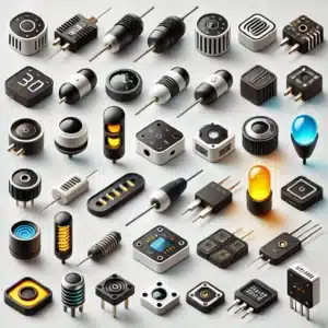
Optical sensors are diverse and sophisticated devices that convert light into electrical signals, playing a crucial role in numerous technological applications. These sensors come in various forms, each designed to detect and measure specific aspects of light, from simple presence detection to complex spectral analysis. The diversity of optical sensors reflects the wide range of light-based phenomena they can measure and the multitude of applications they serve across industries.
The classification of optical sensors can be approached from multiple angles, considering factors such as their detection mechanism, output signal type, spectral range, or specific application. This multifaceted nature of optical sensor categorization allows for a comprehensive understanding of their capabilities and potential uses. However, for practical purposes, it’s often most useful to focus on key types that represent fundamental technologies and widespread applications in the field. Nine specific types of optical sensors have been chosen to provide a comprehensive overview of the field. This selection encompasses a range of technologies from simple to complex, spans various spectral ranges, and includes sensors with diverse industrial applications. Both well-established and innovative technologies are represented, offering insight into the field’s development and future directions:
- Photodiodes
- Phototransistors
- Light-Dependent Resistors (LDRs)
- Photomultiplier Tubes (PMTs)
- Charge-coupled devices (CCDs)
- Complementary Metal-Oxide-Semiconductor (CMOS) sensors
- Fiber Optic Sensors
- Infrared Sensors
- Ultraviolet Sensors
These classification methods provide additional perspectives on the diverse world of optical sensors, highlighting the various ways they can be categorized based on their characteristics and uses. Each classification offers valuable insights into the design, operation, and application of different optical sensors.

Types of Optical Sensors Specification in Table
| Optical Sensor Type | Key Features | Types | Common Applications | Advantages | Disadvantages | Cost |
| Photodiodes | Convert light to electrical current operate in photovoltaic or photoconductive modes. | PN, PIN, Avalanche, Schottky | Light measurement, optical communications, solar cells | Fast response, linear response, high-speed operation, compact size | Temperature-dependent, low current for low light | Low to moderate |
| Phototransistors | Higher sensitivity than photodiodes due to internal gain | BJT, FET | Encoders, card readers, security systems | Higher sensitivity, higher current output, relatively inexpensive | Limited voltage handling, vulnerable to electrical surges | Low to moderate |
| Light-Dependent Resistors (LDRs) | Change resistance based on light intensity | Intrinsic, Extrinsic | Automatic lights, light meters, smoke detectors | Low cost, simple to use, sensitive to a wide range of light frequencies | Slow response, affected by temperature | Low |
| Photomultiplier Tubes (PMTs) | Extremely sensitive, can detect single photons | Head-on type, Side-on type | Low light spectroscopy, nuclear physics, astronomy | Very high sensitivity, high gain, low noise, fast response | Fragile, require high voltage, expensive | High |
| Charge-Coupled Devices (CCDs) | An array of linked capacitors convert photons to electrical charges | Full-frame, Frame-transfer, Interline | Digital cameras, scanners, astronomical telescopes | High sensitivity, low noise, good image quality | Slower readout, more complex, higher power consumption | Moderate to high |
| CMOS Sensors | Integrate image capture and processing on single chip | Standard, BSI, Stacked, Global shutter | Smartphones, security cameras, automotive cameras | Lower power consumption, faster readout, flexible readout options | Historically lower image quality (gap narrowing) | Moderate |
| Fiber Optic Sensors | Use optical fibers to detect physical quantities | Intrinsic, Extrinsic, Distributed, Point, Interferometric | Structural health monitoring, oil and gas industry, medical devices | Immune to EMI, distributed sensing capability, suitable for harsh environments | Higher initial cost, complex system design, fragility of fibers | Moderate to high |
| Infrared Sensors | Detect infrared radiation | Active, Passive, Thermal, Quantum | Motion detection, gas analysis, night vision | Non-contact measurement, detect heat and motion in darkness, long lifespan | Limited penetration through solids, affected by environmental factors | Low to moderate |
| Ultraviolet Sensors | Detect and measure ultraviolet radiation | Photodiode, Photoresistor, UV phototubes, CCD UV sensors | Environmental monitoring, water purification, fire detection | High UV sensitivity, fast response, non-contact measurement | Sensitivity to temperature, potential degradation over time | Moderate to high |
What are Photodiodes?

Photodiodes are semiconductor devices that convert light energy into electrical current. They are essentially p-n junction diodes sensitive to photon radiation, including visible light, infrared, ultraviolet, X-rays, and gamma rays. Photodiodes function as photo detectors, light detectors, or photo sensors, typically operating in reverse bias conditions. Common materials used in photodiodes include Silicon, Germanium, and Indium gallium arsenide.
Working Principle of Photodiodes
Photodiodes operate based on the inner photoelectric effect. When photons with sufficient energy strike the diode, they create electron-hole pairs in the depletion region or within one diffusion length of it. The built-in electric field of the depletion region separates these charge carriers, with holes moving toward the anode and electrons toward the cathode, generating a photocurrent. The total current through the photodiode is the sum of this photocurrent and the dark current (current in the absence of light). The photocurrent is generally linearly proportional to the irradiance for a given spectral distribution.
Applications of Photodiodes
Photodiodes find wide-ranging applications across various fields:
- Consumer electronics (CD players, smoke detectors, remote control receivers)
- Light measurement devices (camera light meters, street lighting controls)
- Medical applications (computed tomography detectors, immunoassay instruments, pulse oximeters)
- Optical communications and lighting regulation
- Scientific and industrial light intensity measurement
- Solar cells for power generation
- Safety electronics (fire and smoke detectors)
- Optocouplers for circuit isolation
- Character recognition circuits
- Logic and detection circuits
Types of Photodiodes
PN photodiode: This basic type consists of a simple p-n junction, useful in low-light scenarios as it doesn’t require reverse bias. Its wider depletion region enhances light sensitivity. PN photodiodes can operate in both photovoltaic (zero bias) and photoconductive (reverse bias) modes, making them versatile.
PIN photodiode: Featuring an intrinsic semiconductor layer between p-type and n-type regions, the PIN photodiode has an increased depletion region width for better light absorption and efficiency. It offers faster response times and higher quantum efficiency, suitable for applications requiring quick response or high sensitivity.
Avalanche photodiode: Operating at a strong reverse bias, this photodiode uses an internal gain mechanism to detect very low light levels. The high electric field causes a multiplication effect, making it capable of single-photon detection in some cases. However, it requires careful control of bias voltage and temperature.
Schottky photodiode: Replacing the p-n junction with a metal-semiconductor junction, this type provides fast response times and long-wavelength detection. It is useful in applications needing rapid switching or near-infrared sensitivity, though it typically has a higher dark current compared to p-n junction photodiodes.
Advantages of Photodiodes
- Quick response to light exposure
- Linear response to light intensity
- High-speed operation
- Lightweight and compact size
- Wide spectral response (e.g., silicon photodiodes respond to 190-1100 nm wavelengths)
- Relatively low cost
- More linear response compared to photoconductors
Disadvantages of Photodiodes
- Temperature-dependent properties, similar to other semiconductor devices
- Low reverse current for low illumination levels
- Not suitable for extremely low light intensity measurements (alternatives like avalanche photodiodes or photomultiplier tubes are used instead)
- In photoconductive mode, they may exhibit more electronic noise due to dark current or avalanche effects
What are Phototransistors?

Phototransistors are semiconductor devices that sense light levels and alter the current flowing between the emitter and collector based on the intensity of light received. They are more sensitive than photodiodes due to the gain provided by their bipolar transistor structure. Phototransistors are essentially specialized bipolar transistors optimized for light sensitivity, making them ideal for many light-sensing applications.
Working Principle of Phototransistors
Phototransistors operate based on the principle that light striking the semiconductor frees electrons and holes, causing current to flow in the base region. They are typically used with the base connection left open circuit. When light enters the base region, it generates electron-hole pairs, mainly in the reverse-biased base-collector junction. These charge carriers move under the electric field’s influence, providing base current and causing electron injection into the emitter. The resulting photodiode current is then multiplied by the transistor’s current gain (β).
Applications of Phototransistors
Phototransistors are used in a wide variety of electronic circuit designs, including:
- Encoders for speed and rotation direction measurement
- Card readers
- Security systems
- Infrared detectors
- Lighting control systems
- Optocouplers
- Counting systems
- Human detection devices
- Consumer electronics (TVs, air conditioners, digital photo frames, PCs, laptops)
- Automatic switches for lighting equipment
- IP cameras
Types of Phototransistors
- BJT Phototransistor: In the absence of light, it allows a low leakage current (around 100 nA) between the collector and emitter. When exposed to light, it can handle currents up to 50mA, distinguishing it from photodiodes.
- FET Phototransistor: This type has two terminals connected internally through the collector and emitter (or source and drain in FETs). The base terminal reacts to light and controls the current flow between the terminals.
Advantages of Phototransistors
- Higher sensitivity due to internal gain
- Produce higher current than photodiodes
- Relatively inexpensive and simple to manufacture
- Can be incorporated into integrated circuits
- Fast response time, providing nearly instantaneous output
- Produce a voltage, unlike photoresistors
- Small size allows multiple devices on a single chip
- Offer reasonable speed for many applications
Disadvantages of Phototransistors
- Limited voltage handling capability (silicon-based devices typically can’t handle over 1,000 Volts)
- Vulnerable to electrical surges, spikes, and electromagnetic energy
- Not as fast as some other light-sensitive components like photodiodes
- More restricted electron movement compared to devices like electron tubes
- May be damaged in applications with exposure to transient voltage spikes and surges
What are Light-Dependent Resistors (LDRs)?

Light-dependent resistors (LDRs), also known as photoresistors or photocells, are electronic components that change their resistance in response to light intensity. They are passive devices made from semiconductor materials, typically without a PN junction. LDRs are designed specifically for their light sensitivity, with their resistance decreasing as the intensity of light increases. They are available in various sizes, including 5mm, 8mm, 12mm, and 25mm dimensions.
Working Principle of Light-Dependent Resistors (LDRs)
LDRs work on the principle of photoconductivity. When light falls on the photoconductive material of the LDR, it absorbs the energy. If this energy is greater than the material’s bandgap energy, electrons in the valence band become excited and move to the conduction band. This increases the conductivity of the material proportionally to the increase in light intensity. In the darkness, an LDR can have a resistance as high as 10^12 Ohms, which decreases significantly with increased light exposure.
Applications of Light-Dependent Resistors (LDRs)
LDRs are used in various applications, including:
- Automatic street lights and security lights
- Light meters in cameras
- Clock radios with automatic light adjustment
- Simple smoke detector alarms
- Optical circuit designs
- Photo proximity switches
- Laser-based security systems
- Solar street lamps
- Dynamic compressors in audio equipment
- Burglar alarms
- Light intensity detection and measurement
Types of Light-Dependent Resistors (LDRs)
- Intrinsic Photoresistors: Made with pure semiconductors like silicon or germanium without any doping. They respond to light when incident photons have enough energy to excite electrons from the valence band to the conduction band.
- Extrinsic Photoresistors: Use doped semiconductors with added impurities like phosphorus. These are generally designed for longer wavelengths of light, with a tendency towards infrared (IR) sensitivity.
Advantages of Light-Dependent Resistors (LDRs)
- Low cost
- Simple to use and integrate into circuits
- Low power consumption
- Sensitive to a wide range of light frequencies
- Large resistance change (from megohms in darkness to hundreds of ohms in bright light)
- Passive devices requiring no external power for operation
- Useful in a wide variety of light-sensing applications
Disadvantages of Light-Dependent Resistors (LDRs)
- Slow response to changes in light intensity compared to other light-sensing devices
- Affected by temperature changes, which can influence their resistance
- Significant variation in resistance between individual components, making consistent performance challenging
- Less precise than some other light-sensing technologies
- Not suitable for applications requiring quick response times
- Some materials used (like cadmium sulfide) may be restricted due to environmental concerns
What are Photomultiplier Tubes (PMTs)?

Photomultiplier Tubes (PMTs) are extremely sensitive detectors of light in the ultraviolet, visible, and near-infrared ranges of the electromagnetic spectrum. They are vacuum tubes that can multiply the current produced by incident light by as much as 100 million times (108 or 160 dB), enabling the detection of individual photons when the incident flux of light is low. PMTs are among the most sensitive light sensors available and are used to detect faint light signals in various scientific and industrial applications.
Working Principle of Photomultiplier Tubes (PMTs)
PMTs operate based on the photoelectric effect and electron multiplication. When light enters through an incident window and strikes a photocathode, it generates photoelectrons. These photoelectrons are attracted and accelerated by a high voltage applied across the tube. The accelerated electrons then strike a series of dynodes, each at a higher potential than the previous one. Each dynode emits secondary electrons when struck, creating an electron cascade. This process is repeated through typically 9 to 12 dynode stages, with the electron count multiplying at each stage. Finally, the multiplied electrons reach the anode, producing a measurable output current. The multiplication factor can be adjusted by controlling the applied high voltage, allowing for adaptability to different light intensities.
Applications of Photomultiplier Tubes (PMTs)
PMTs are used in a wide range of applications, including:
- Low light level spectroscopy (e.g., Raman and fluorescence spectroscopy)
- Nuclear and particle physics experiments
- Astronomy and astrophysics
- Medical diagnostics and imaging (e.g., gamma cameras, blood analysis)
- Radiation detection (e.g., scintillation counters, survey meters)
- Environmental monitoring (e.g., NOx and SOx meters)
- Scanning electron microscopes as secondary electron detectors
- High-end image scanners (drum scanners)
- Motion picture film scanning (telecine)
- Night vision devices
- Laser light scattering studies
Types of Photomultiplier Tubes (PMTs)
PMTs can be categorized into two main types based on their structure:
- Head-on type: The photosensitive area is located at the tip of the tube. This design allows for a larger detection area and more uniform sensitivity across the photocathode surface. Head-on PMTs are often preferred in applications requiring high collection efficiency or uniform spatial response.
- Side-on type: The photosensitive area is located at the side of the tube. This configuration can be advantageous in certain geometrical setups, particularly where space is limited. Side-on PMTs often have a more compact design and can be useful in applications where the light source is positioned perpendicular to the detector axis.
Additionally, PMTs can vary based on:
- Number of dynodes (typically 9 to 12)
- Photocathode materials (different wavelength sensitivities)
- Photosensitive surface sizes
Advantages of Photomultiplier Tubes (PMTs)
- Extremely high sensitivity and ability to detect single photons
- High gain (up to 108)
- Low noise
- Fast response time (high frequency response)
- Large collection area
- Wide spectral response
- High output signal-to-noise ratio
- Adjustable gain through voltage control
- High stability
- Low transport delay
Disadvantages of Photomultiplier Tubes (PMTs)
- Mechanically fragile due to glass envelope construction
- Physically large with limited shapes and sizes
- Require stable high voltage power supplies
- Expensive (can cost hundreds of dollars)
- Sensitivity to magnetic fields, requiring magnetic shielding in critical applications
- May require cooling to liquid nitrogen temperatures for noise reduction in some applications
- Limited in durability compared to solid-state devices
- Potential for damage from exposure to high light levels
What are charge-coupled devices (CCDs)?

Charge-Coupled Devices (CCDs) are integrated circuits containing an array of linked or coupled, capacitors that function as light-sensitive image sensors. Invented in 1969 at Bell Labs by George Smith and Willard Boyle, CCDs convert photons into electrical charges, allowing for the capture and processing of digital images. Each CCD consists of a photoactive region made of an epitaxial layer of silicon and a transmission region composed of a shift register. CCDs break down image elements into pixels, with each pixel converting light intensity into a proportional electrical charge.
Working Principle of charge-coupled devices (CCDs)
CCDs operate based on the photoelectric effect. When light falls on the photoactive region, it causes each capacitor (representing a pixel) to accumulate an electric charge proportional to the light intensity at that location. After exposure, a control circuit triggers each capacitor to transfer its charge to its neighbor, operating as a shift register. The last capacitor in the array transfers its charge to a charge amplifier, which converts it into a voltage. This process is repeated, converting the entire array’s contents into a sequence of voltages. These voltages are then sampled, digitized, and stored in memory for digital devices or processed into a continuous analog signal for analog devices.
Applications of charge-coupled devices (CCDs)
CCDs have been widely used in various fields, including:
- Digital cameras (professional and consumer)
- Scanners and barcode readers
- Medical imaging equipment
- Astronomical telescopes and satellite imagery
- Microscopes and scientific instruments
- Machine vision for robotics
- Optical character recognition (OCR)
- Meteorological imaging and radar systems
- Spectroscopy and other scientific research applications
Types of Charge-Coupled Devices (CCDs)
CCDs can be implemented in several different architectures, primarily distinguished by their approach to shuttering and readout:
- Full-frame CCDs: The entire sensor area is light-sensitive and used for image capture. After exposure, the image is read out one row at a time, requiring a mechanical shutter to prevent smearing. This design maximizes light-gathering, making it ideal for high-end scientific and astronomical applications where light sensitivity is crucial.
- Frame-transfer CCDs: The sensor is split into two areas: one for image capture and one for storage. The light-sensitive half captures the image then rapidly transfers it to the storage area, allowing the next exposure to start immediately. The storage area is masked to prevent exposure during readout. This design offers faster operation and reduces the need for a mechanical shutter, suitable for video applications.
- Interline CCDs: Alternating columns of pixels are masked for storage. After exposure, charges are quickly shifted sideways into these light-shielded columns, enabling very fast readout and eliminating the need for a mechanical shutter. Interline CCDs are commonly used in consumer and professional video cameras due to their ability to handle rapid successive exposures.
Advantages of charge-coupled devices (CCDs)
- Higher sensitivity and lower noise due to enhanced surface use (higher fill factor)
- Fewer defective pixels due to simpler structure
- Better image homogeneity thanks to the central A/D converter
- Historically superior image quality compared to early CMOS sensors
- High light sensitivity, making them suitable for low-light applications
- Linear response to light intensity, beneficial for scientific applications
Disadvantages of charge-coupled devices (CCDs)
- Slower readout speed due to the single central A/D converter
- No direct pixel access, as the sensor must be read out serially
- More complex camera layout, leading to larger and more expensive cameras
- Higher energy consumption of the entire camera system
- More prone to smearing and blooming effects when overexposed compared to CMOS sensors
- Gradually being replaced by CMOS sensors in many applications due to technological advancements in CMOS technology
What are Complementary Metal-Oxide-Semiconductor (CMOS) sensors?

Complementary Metal-Oxide-Semiconductor (CMOS) sensors are semiconductor devices that capture images by converting light into electrical signals. Developed initially by NASA for space imaging, CMOS sensors have become the dominant technology in modern digital cameras and imaging devices. These sensors consist of an array of light-sensitive photodiodes, each representing a pixel, surrounded by transistors that amplify and process the captured light signals. CMOS technology allows for the integration of image capture, processing, and readout circuitry on a single chip, leading to more compact and energy-efficient imaging systems.
Working Principle of Complementary Metal-Oxide-Semiconductor (CMOS) sensors
CMOS sensors operate based on the photoelectric effect. When light falls on the photodiodes, it generates electron-hole pairs. The electrons are collected in potential wells, creating a charge proportional to the light intensity. Unlike CCDs, each pixel in a CMOS sensor has its own charge-to-voltage conversion and typically includes amplifiers, noise-correction, and digitization circuits. This design allows for direct addressing of individual pixels and on-chip processing.
The typical process flow is as follows:
- Light photons strike the photodiode array.
- Electrons are generated and collected in potential wells.
- The charge is converted to voltage at each pixel site.
- On-chip circuitry amplifies and processes the signal.
- An analog-to-digital converter (ADC) converts the signals to digital data.
- The digital data is processed to form the final image.
Applications of Complementary Metal-Oxide-Semiconductor (CMOS) sensors
CMOS sensors are widely used in various applications, including:
- Smartphones and consumer digital cameras
- Security and surveillance systems
- Automotive cameras (e.g., backup cameras, driver assistance systems)
- Medical imaging devices
- Industrial machine vision systems
- Webcams and video conferencing equipment
- Drones and aerial photography
- Barcode scanners and document scanners
- Astronomy and space exploration
- High-speed photography and slow-motion video capture
Types of Complementary Metal-Oxide-Semiconductor (CMOS) sensors
While CMOS sensors don’t have distinct architectural types like CCDs, they can be categorized based on their design and functionality:
- Standard CMOS sensors: These are the most common type used in a wide range of consumer and professional devices.
- Backside-illuminated (BSI) CMOS sensors: These sensors have their circuitry behind the photodiode layer, allowing more light to reach the photosensitive area and improving low-light performance.
- Stacked CMOS sensors: These sensors separate the photodiode layer from the processing circuitry, allowing for more complex on-chip processing and faster readout speeds.
- Global shutter CMOS sensors: Unlike the more common rolling shutter designs, these sensors capture the entire image simultaneously, reducing motion artifacts in fast-moving scenes.
Advantages of Complementary Metal-Oxide-Semiconductor (CMOS) sensors
- Lower power consumption compared to CCD sensors
- On-chip integration of processing circuitry, allowing for smaller camera sizes
- Faster readout speeds, enabling high frame rates
- Flexible readout options, including windowing and binning
- Reduced blooming effects compared to CCD sensors
- Lower manufacturing costs due to standard semiconductor processes
- Higher sensitivity in the near-infrared (NIR) range
- Ability to implement advanced features like on-chip image processing and artificial vision
Disadvantages of Complementary Metal-Oxide-Semiconductor (CMOS) sensors
- Lower fill factor (ratio of light-sensitive area to total pixel area) compared to CCDs, potentially reducing light sensitivity
- Greater pixel-to-pixel variations due to manufacturing tolerances, leading to increased fixed pattern noise
- Historically lower image quality compared to CCDs, especially in low-light conditions (though this gap has narrowed significantly in recent years)
- More complex pixel-level circuitry can lead to increased read noise
- Rolling shutter effects in most CMOS sensors can cause image distortion in fast-moving scenes
- Limited dynamic range compared to some specialized CCD sensors
Despite these disadvantages, ongoing technological advancements have significantly improved CMOS sensor performance, making them the preferred choice for most modern imaging applications.
What are fiber optic sensors?

Fiber optic sensors are devices that use optical fibers to detect and measure various physical quantities such as strain, temperature, pressure, acceleration, and chemical concentrations. These sensors can be categorized into two main types: intrinsic sensors, where the optical fiber itself acts as the sensing element, and extrinsic sensors, where the optical fiber is used to transmit signals from a remote sensor to processing electronics. Fiber optic sensors leverage the properties of light transmission through optical fibers to provide highly sensitive and versatile sensing capabilities across a wide range of applications.
Working Principle of Fiber Optic Sensors
Fiber optic sensors operate based on the principle that light transmitted through an optical fiber can be modulated by external physical, chemical, or biological influences. Light generation occurs when a laser or superluminescent source emits light into the optical fiber, which then travels through the fiber core, guided by total internal reflection at the core-cladding interface. During modulation, the measured quantity affects the properties of the transmitted light, such as intensity, phase, polarization, wavelength, or transit time. A photodetector at the fiber’s end converts the modulated light signal into an electrical signal, which is then analyzed to determine the value of the measured quantity. For distributed sensing, techniques like optical time-domain reflectometry (OTDR) or optical frequency domain reflectometry (OFDR) are employed to ascertain the location and magnitude of the measured quantity along the fiber length, allowing precise monitoring and measurement over the entire fiber length.
Applications of fiber optic sensors
Fiber optic sensors find use in a wide range of applications, including:
- Structural health monitoring of buildings, bridges, and dams
- Oil and gas industry for well monitoring and pipeline leak detection
- Aerospace for aircraft and spacecraft monitoring
- Power systems for temperature monitoring in electrical transformers
- Medical devices for minimally invasive diagnostics and treatments
- Environmental monitoring for pollution detection and seismic activity
- Industrial process control and automation
- Security systems for perimeter monitoring
- Smart grids for power line monitoring
- Geotechnical and geophysical monitoring in mining and tunneling
Types of fiber optic sensors
Fiber optic sensors can be classified based on various criteria. Some main types include:
- Intensity-based sensors: Measure changes in light intensity
- Interferometric sensors: Use interference patterns to detect changes
- Distributed sensors: Measure quantities along the entire length of the fiber
- Fiber Bragg Grating (FBG) sensors: Use periodic variations in the fiber’s refractive index
- Extrinsic sensors: Use fibers to transmit light to and from an external sensing element
- Intrinsic sensors: Use the fiber itself as the sensing element
- Point sensors: Measure at specific points along the fiber
- Quasi-distributed sensors: Measure at multiple pre-determined points
Based on the sensing mechanism, they can also be categorized as:
- Photoelectric sensors: Including through-beam, retroreflective, and diffuse reflective types
- Plastic fiber sensors: Using plastic optical fibers for flexibility and cost-effectiveness
- Glass fiber sensors: Using glass fibers for high-temperature applications
Advantages of fiber optic sensors
- Immunity to electromagnetic interference (EMI) and radio frequency interference (RFI)
- Electrically passive operation, allowing use in high-voltage or flammable environments
- High sensitivity and wide dynamic range
- Capability for distributed sensing over long distances
- Small size and light weight
- Resistance to harsh environments, including high temperatures and corrosive conditions
- Multiplexing capability, allowing multiple sensors on a single fiber
- High bandwidth and fast response times
- No electrical power is required at the sensing point
- Long-term stability and reliability
Disadvantages of fiber optic sensors
- Higher initial cost compared to conventional sensors
- Complexity in system design and signal processing
- Fragility of optical fibers, requiring careful handling during installation
- Potential for signal loss or degradation over very long distances
- Sensitivity to mechanical perturbations, which can introduce noise
- Limited to measuring quantities that can affect light properties
- Requires specialized equipment and expertise for installation and maintenance
- Potential for cross-sensitivity to multiple parameters
- Challenges in achieving absolute measurements without proper referencing
- Limited availability of standardized components and interfaces compared to electrical sensors
Despite these disadvantages, the unique capabilities and advantages of fiber optic sensors make them increasingly popular in many specialized and demanding applications where conventional sensors are inadequate or impractical.
What are Infrared Sensors?

Infrared (IR) sensors are optoelectronic devices that detect and measure infrared radiation in their surrounding environment. These sensors are sensitive to electromagnetic radiation in the infrared spectrum, typically ranging from 780 nm to 50 µm wavelengths. IR sensors can detect heat and motion by measuring the infrared radiation emitted by objects. Discovered accidentally by astronomer William Herschel in 1800, infrared radiation is invisible to the human eye but can be detected by electronic devices designed for this purpose. Any object with a temperature above about five degrees Kelvin emits infrared radiation, making IR sensors versatile tools for various applications.
Working Principle of Infrared Sensors
The working principle of infrared sensors depends on whether they are active or passive:
- Active IR Sensors:
- Consists of two main components: a light-emitting diode (LED) and a receiver
- The LED emits infrared radiation
- When an object enters the sensor’s range, the IR light reflects off the object
- The receiver detects the reflected IR radiation
- The sensor processes this information to determine the presence or proximity of objects
- Passive IR (PIR) Sensors:
- Only detect infrared radiation without emitting it
- Typically comprises two strips of pyroelectric material, an infrared filter, and a Fresnel lens
- The pyroelectric material detects changes in infrared radiation levels
- When a warm object (like a person) moves across the sensor’s field of view, it creates a difference in IR levels between the two pyroelectric elements
- This difference triggers the sensor to send an electronic signal
Both types of sensors convert the detected infrared radiation into an electrical signal, which can then be processed and used to trigger various actions or measurements.
Applications of Infrared Sensors
Infrared sensors find use in a wide range of applications, including:
- Motion detection in security systems and automatic doors
- Proximity sensing in mobile devices and robotics
- Gas analysis and detection in industrial processes
- Flame detection in fire alarm systems
- Non-contact temperature measurement in various industries
- Remote sensing in environmental monitoring
- Night vision technology in surveillance and military applications
- Optical communication systems
- Heat loss detection in buildings
- Presence detection for energy-efficient lighting systems
- Object counting and positioning in manufacturing
- Medical diagnostics and thermal imaging
Types of Infrared Sensors
Infrared sensors can be categorized based on their detection mechanism and operational principles:
- Based on emission and detection:
- Active IR sensors: Emit and detect IR radiation
- Passive IR (PIR) sensors: Only detect IR radiation
- Based on operational principles:
- Thermal IR sensors: a. Pyroelectric detectors: Detect changes in heat b. Bolometers: Measure temperature changes in a material c. Thermopiles: Use the Seebeck effect to measure temperature differences d. Golay cells: Measure pressure changes in a gas volume
- Quantum IR sensors: a. Photodiodes: Use the inner photoelectric effect b. Photoresistors: Change electrical resistance based on received radiation
- Based on wavelength range:
- Near-infrared (NIR) sensors
- Short-wavelength infrared (SWIR) sensors
- Mid-wavelength infrared (MWIR) sensors
- Long-wavelength infrared (LWIR) sensors
Advantages of Infrared Sensors
- Non-contact measurement capability
- Ability to detect motion and heat in darkness
- Long operational life due to low power consumption
- Fast response time compared to other temperature sensors
- Secure communication in point-to-point applications
- Capability to measure distance to sensitive objects
- Compact size and affordability
- Good stability over time
- Immunity to electromagnetic interference
- High repeatability and accuracy in measurements
- Ability to detect objects at short ranges (less than 10 mm)
- No corrosion or oxidation affecting accuracy
Disadvantages of Infrared Sensors
- Limited penetration through solid objects (walls, doors)
- Susceptibility to interference from smoke, dust, fog, and strong sunlight
- Potential for eye damage from high-intensity infrared radiation
- Limited range compared to some other sensing technologies
- Lower data transmission rates compared to wired transmission
- Difficulty in controlling objects not in the line of sight
- Limited ability to distinguish between similar heat sources
- Potential for false alarms due to rapid environmental temperature changes
- Reduced effectiveness in environments with high ambient infrared radiation
- Need for careful calibration and positioning for accurate measurements
- Sensitivity to ambient temperature fluctuations
- Higher cost for more advanced or specialized IR sensing applications
What are Ultraviolet Sensors?

Ultraviolet (UV) sensors are specialized electronic devices designed to detect and measure ultraviolet radiation in the environment. These sensors are sensitive to electromagnetic radiation with wavelengths shorter than visible light but longer than X-rays, typically in the range of 10-400 nanometers. UV sensors convert ultraviolet radiation into electrical signals, allowing for the quantification and monitoring of UV exposure. They play a crucial role in various fields, from environmental monitoring to industrial processes, by providing accurate measurements of UV intensity and dosage.
Working Principle of Ultraviolet Sensors
Ultraviolet sensors operate based on the photoelectric effect, where UV radiation causes the emission of electrons from a material. The general working principle involves:
- UV radiation detection: The sensor’s active element (usually a photodiode or photoresistor) is exposed to UV light.
- Photoelectric conversion: When UV photons strike the sensor’s active element, they excite electrons, causing them to move and generate an electrical current.
- Signal processing: The generated electrical current is proportional to the intensity of the incident UV radiation. This current is then amplified and converted into a usable electrical signal.
- Output generation: The processed signal is converted into a digital or analog output, which can be read by connected devices or systems.
There are two main types of UV sensors based on their detection mechanism:
- Photodiode-type UV sensors: These use a silicon photodiode to measure illuminance. They provide more accurate measurements and are suitable for scientific applications.
- Photoresistor UV sensors: These measure changes in electrical resistance caused by UV light. They are less accurate but simpler and often used for basic on/off detection of UV light.
Applications of Ultraviolet Sensors
UV sensors find use in a wide range of applications, including:
- Environmental monitoring and weather stations
- Skin protection and sunburn prevention
- Water and air purification systems
- Pharmaceutical industry for drug photostability testing
- Automotive industry for UV-sensitive materials testing
- Robotics and automation
- Fire detection systems
- Security applications (e.g., in access cards and banknotes)
- Biochemical research and DNA analysis
- Industrial manufacturing processes
- Structural health monitoring of UV-sensitive materials
- Sterilization and disinfection systems in hospitals
- UV curing processes in printing and coating industries
- Solar radiation measurement in renewable energy systems
- Horticulture for monitoring plant growth conditions
Types of Ultraviolet Sensors
UV sensors can be categorized based on their detection mechanism and the specific UV range they target:
- Based on detection mechanism:
- Photodiode UV sensors
- Photoresistor UV sensors
- UV phototubes
- Charge-coupled device (CCD) UV sensors
- Based on UV spectrum range:
- UVA sensors (315-400 nm)
- UVB sensors (280-315 nm)
- UVC sensors (100-280 nm)
- Based on application:
- UV index sensors
- Germicidal UV detectors
- Photostability sensors
- UV spectrum sensors
- Solar UV irradiance sensors
Advantages of Ultraviolet Sensors
- High sensitivity to UV radiation
- Ability to measure a wide range of UV intensities
- Fast response time to changes in UV levels
- Non-contact measurement capability
- Long operational life with proper maintenance
- Compact size and ease of integration into various systems
- Capability to provide real-time UV exposure data
- Versatility in applications across multiple industries
- Contribute to improved safety measures in UV-sensitive environments
- Enable precise control in UV-dependent processes
- Support energy efficiency in UV-based systems
- Facilitate research in UV-related fields
Disadvantages of Ultraviolet Sensors
- Sensitivity to temperature fluctuations, which can affect accuracy
- Potential for degradation over time due to prolonged UV exposure
- Limited selectivity – may respond to other light sources besides UV
- Higher cost for high-precision UV sensors
- Requirement for regular calibration to maintain accuracy
- Sensitivity to physical damage, especially in harsh environments
- Potential interference from other electromagnetic radiation sources
- Limited penetration through certain materials, restricting some applications
- Variation in sensitivity across different UV wavelengths
- Complexity in interpreting raw data for some applications
- Need for specialized knowledge for proper installation and maintenance
- Possible overestimation of UV exposure in certain conditions (e.g., reflective surfaces)
Conclusion
Optical sensors play a crucial role in modern technology, bridging the gap between the physical world of light and the digital realm of electrical signals. From simple photodiodes to complex charge-coupled devices and cutting-edge CMOS sensors, these devices have revolutionized numerous fields, including digital imaging, telecommunications, medical diagnostics, and environmental monitoring. Each type of optical sensor, whether it’s a photomultiplier tube offering extreme sensitivity or a fiber optic sensor providing distributed sensing capabilities, brings unique advantages to specific applications.
The evolution of optical sensor technology has led to increased precision, sensitivity, and versatility in light detection and measurement. While some technologies like CCDs are gradually being replaced by more advanced options like CMOS sensors in many applications, each type of optical sensor continues to find its niche based on its particular strengths. The ongoing advancements in this field, such as the development of backside-illuminated and stacked CMOS sensors, promise even greater capabilities in the future.
As we continue to push the boundaries of what’s possible in fields like autonomous vehicles, augmented reality, and space exploration, optical sensors will undoubtedly play an increasingly important role. Their ability to provide non-contact measurements, operate in harsh environments, and detect a wide range of light spectra makes them indispensable tools in our increasingly digital and interconnected world.
FAQ about Type of Optical Sensors
- What is the main difference between CCD and CMOS sensors?
The main difference lies in how they process the light signal. In CCDs, the charge from each pixel is transferred sequentially to a common output structure for processing, while in CMOS sensors, each pixel has its own charge-to-voltage conversion and typically includes amplifiers, noise-correction, and digitization circuits, allowing for direct addressing of individual pixels and on-chip processing. - Why are fiber optic sensors immune to electromagnetic interference?
Fiber optic sensors are immune to electromagnetic interference because they use light signals instead of electrical signals. The optical fibers are made of non-conductive materials, so they are not affected by external electromagnetic fields. - What are the advantages of using infrared sensors?
Infrared sensors offer several advantages, including non-contact measurement capability, ability to detect motion and heat in darkness, long operational life due to low power consumption, fast response time, and immunity to electromagnetic interference. - How do photomultiplier tubes (PMTs) achieve such high sensitivity?
PMTs achieve high sensitivity through a process of electron multiplication. When a photon strikes the photocathode, it releases an electron. This electron is then accelerated and strikes a series of dynodes, each of which releases multiple secondary electrons. This cascade effect can multiply the original signal by as much as 100 million times. - What is the difference between active and passive infrared sensors?
Active infrared sensors both emit and detect infrared radiation. They typically consist of an IR LED that emits infrared light and a receiver that detects the reflected light. Passive infrared (PIR) sensors, on the other hand, only detect infrared radiation emitted by objects in their field of view without emitting any radiation themselves. - How do ultraviolet sensors work?
Ultraviolet sensors work based on the photoelectric effect. When UV photons strike the sensor’s active element (usually a photodiode or photoresistor), they excite electrons, causing them to move and generate an electrical current. This current is then amplified and converted into a usable electrical signal proportional to the intensity of the incident UV radiation.