
The world of electronics is vast and complex, with many different components and devices that work together to create the technology we use every day. One such component is the amplifier, which is used to increase the amplitude of an electrical signal. There are many different types of amplifiers, each with its own unique characteristics and applications. In this blog post, we will explore some of the most common types of amplifiers and their uses in various electronic devices.
Different Types of Amplifiers
There are many different types of amplifiers, each with its own unique characteristics and applications. Here are some of the most common types of amplifiers:
- Voltage-Controlled Amplifiers
- Current-Controlled Amplifiers
- Power Amplifiers
- Transconductance Amplifier
- Transresistance Amplifier
- Instrument Amplifiers
- Operational Amplifiers (Op-Amps)
- Valve (or) Vacuum Tube Amplifiers
- Distributed Amplifiers
Types of Amplifiers Specifications in Table
| Amplifier Type | Advantages | Disadvantages | Control Input | Usage/Applications |
|---|---|---|---|---|
| Voltage-Controlled Amplifiers | Versatility, variable gain control | Dependence on load resistance, potential instability | Voltage | Audio systems, radio signals, telecom signals |
| Current-Controlled Amplifiers | Ideal for low-impedance loads, simpler design | More sensitive to load variations, less common | Current | Current-mode communication systems, some audio applications |
| Power Amplifiers | Can drive high-power loads, efficient | Possible distortion at high frequencies, size, and weight | Voltage/Current | Broadcasting systems, audio systems, wireless communication |
| Transconductance Amplifiers | High input impedance, low output impedance | Lower voltage gain, complex design | Voltage | Signal processing, automatic control systems |
| Transresistance Amplifiers | Accurate current-to-voltage conversion | Input impedance varies, and complex design | Current | Optical receivers, some integrated circuits |
| Instrument Amplifiers | High gain accuracy, high input impedance | Complex circuitry, higher cost | Voltage | Test equipment, measurement devices, data acquisition systems |
| Operational Amplifiers (Op-Amps) | High gain, high input impedance | Limited bandwidth, potential offset voltage problems | Voltage | Wide range of electronic devices, filters, signal processing |
| Valve (or) Vacuum Tube Amplifiers | Unique sound quality, high voltage gain | Bulky, high power consumption, heat generation | Voltage | High-end audio systems, guitar amplifiers |
| Distributed Amplifiers | High bandwidth, simultaneous amplification | Requires careful design, high cost | Voltage | Broadband applications, oscilloscopes, high-speed digital systems |
Please note that this is a general summary, and specific designs of these amplifiers can vary in their properties. The ‘control input’ column refers to the type of input signal (voltage or current) that mainly influences the output of the amplifier.
What is Voltage-Controlled Amplifiers?
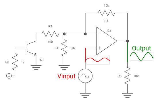
A voltage-controlled amplifier (VCA) is an electronic device that amplifies an input signal by a factor that is controlled by a voltage input. The VCA is a fundamental component in many electronic devices, including audio and synthesizer equipment. Here are some key features of voltage-controlled amplifiers:
Control Input of Voltage-Controlled Amplifiers
The control input of a VCA is a voltage signal that determines the gain of the amplifier. The gain of the VCA is proportional to the control voltage, which means that the output signal level can be controlled by varying the control voltage.
Applications of Voltage-Controlled Amplifiers
Voltage-controlled amplifiers are commonly used in audio and synthesizer equipment. They are used to control the amplitude of an audio signal, which is useful for creating effects such as tremolo, vibrato, and volume control. In synthesizer equipment, VCAs are used to control the amplitude of an oscillator signal, which is useful for creating complex waveforms.
Types of Voltage-Controlled Amplifiers
There are several different types of voltage-controlled amplifiers, including:
- Linear VCAs: These amplifiers provide a linear relationship between the control voltage and the gain of the amplifier. They are commonly used in audio applications.
- Exponential VCAs: These amplifiers provide an exponential relationship between the control voltage and the gain of the amplifier. They are commonly used in synthesizer equipment.
- Logarithmic VCAs: These amplifiers provide a logarithmic relationship between the control voltage and the gain of the amplifier. They are commonly used in audio applications.
Advantages of Voltage-Controlled Amplifiers
One of the main advantages of voltage-controlled amplifiers is that they provide precise control over the amplitude of a signal. This makes them useful for creating complex waveforms and effects in audio and synthesizer equipment. Additionally, VCAs are often used in feedback loops, which can provide increased stability and reduced distortion in electronic circuits.
Disadvantages of Voltage-Controlled Amplifiers
One of the main disadvantages of voltage-controlled amplifiers is that they can introduce noise and distortion into a signal. Additionally, VCAs can be sensitive to temperature changes and other environmental factors, which can affect their performance.
Diagram of Voltage-Controlled Amplifiers
Current-Controlled Amplifiers
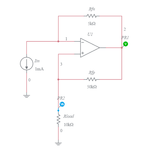
A current-controlled amplifier (CCA) is an electronic device that amplifies an input signal by a factor that is controlled by a current input. The input signal to a CCA controls the current output of the amplifier. Here are some key features of current-controlled amplifiers:
Control Input of Current-Controlled Amplifiers
The control input of a CCA is a current signal that determines the gain of the amplifier. The gain of the CCA is proportional to the control current, which means that the output signal level can be controlled by varying the control current.
Applications of Current-Controlled Amplifiers
Current-controlled amplifiers are commonly used in radio frequency (RF) applications. They are used to control the amplitude of an RF signal, which is useful for creating effects such as modulation and demodulation. CCAs are also used in instrumentation amplifiers, which are used to amplify small signals in measurement applications.
Types of Current-Controlled Amplifiers
There are several different types of current-controlled amplifiers, including:
- Transconductance amplifiers: These amplifiers provide an output current that is proportional to the input voltage. They are commonly used in RF applications.
- Transresistance amplifiers: These amplifiers provide an output voltage that is proportional to the input current. They are commonly used in instrumentation amplifiers.
Advantages of Current-Controlled Amplifiers
One of the main advantages of current-controlled amplifiers is that they provide precise control over the amplitude of a signal. This makes them useful for creating effects such as modulation and demodulation in RF applications. Additionally, CCAs are often used in feedback loops, which can provide increased stability and reduced distortion in electronic circuits.
Disadvantages of Current-Controlled Amplifiers
One of the main disadvantages of current-controlled amplifiers is that they can introduce noise and distortion into a signal. Additionally, CCAs can be sensitive to temperature changes and other environmental factors, which can affect their performance.
Diagram of Current-Controlled Amplifiers
Power Amplifiers
A power amplifier is an electronic device that amplifies an input signal to a level that is suitable for driving a load, such as a speaker or motor. Power amplifiers are used in a wide range of applications, including audio, motor controllers, relay drivers, and more. Here are some key features of power amplifiers:
Applications
Power amplifiers are used in a variety of applications, including audio systems, motor controllers, and relay drivers. In audio systems, power amplifiers are used to amplify the signal from a preamplifier to a level that is suitable for driving a speaker. In motor controllers, power amplifiers are used to control the speed and direction of a motor. In relay drivers, power amplifiers are used to provide the necessary current to activate a relay.
Classes
There are several different classes of power amplifiers, including:
- Class A: These amplifiers provide a linear output with the lowest distortion, but they also have the lowest efficiency level.
- Class B: These amplifiers are biased so that they conduct over half the waveform, and they are commonly used in audio applications.
- Class AB: These amplifiers are a combination of Class A and Class B amplifiers, providing a balance between efficiency and linearity.
- Class C: These amplifiers are biased so that they conduct for less than half the waveform, and they are commonly used in RF applications.
- Class D: These amplifiers use pulse width modulation (PWM) to switch the output stage on and off rapidly, and they are commonly used in audio applications.
- Class E: These amplifiers use resonant circuits to increase efficiency, and they are commonly used in RF applications.
- Class F: These amplifiers use harmonic tuning to increase efficiency, and they are commonly used in RF applications.
Amplifier Class by Conduction Angle
| Amplifier Class | Conduction Angle (°) | Conduction Angle (Formula) |
| Class A | 360° | θ = 360° * t / T, for t = T |
| Class B | 180° | θ = 360° * t / T, for t = T/2 |
| Class AB | Between 180° and 360° | θ = 360° * t / T, for T/2 < t < T |
| Class C | Less than 180° | θ = 360° * t / T, for t < T/2 |
| Class D | Switching (either fully on or fully off) | Not applicable, as it’s either 0° or 360°, switching on and off |
For Class D amplifiers, the conduction angle is not applicable in the traditional sense, because they operate by rapidly switching between fully ON (conducting) and OFF (not conducting). This results in a pulse width modulated signal that is then filtered to retrieve the amplified signal.
Advantages
One of the main advantages of power amplifiers is that they provide high power output, which makes them useful for driving loads such as speakers and motors. Additionally, power amplifiers can be designed to provide high efficiency, which reduces power consumption and heat dissipation.
Disadvantages
One of the main disadvantages of power amplifiers is that they can introduce distortion and noise into a signal. Additionally, power amplifiers can be sensitive to temperature changes and other environmental factors, which can affect their performance.
Transconductance Amplifier
A transconductance amplifier (gm amplifier) is an electronic device that converts an input voltage into an output current. The transconductance is directly proportional to an amplifier bias current, which is used to control the transconductance. Here are some key features of transconductance amplifiers:
Applications
Transconductance amplifiers are used in a variety of applications, including variable frequency oscillators, variable gain amplifiers, and current-controlled filters. These applications exploit the fact that the transconductance gain is a function of the current flowing into the control current pin. Transconductance amplifiers are also used in motor controllers, relay drivers, and audio loudspeaker drivers.
Advantages
One of the main advantages of transconductance amplifiers is that they provide a high output current, which makes them useful for driving loads such as motors and loudspeakers. Additionally, transconductance amplifiers can be designed to provide high efficiency, which reduces power consumption and heat dissipation.
Disadvantages
One of the main disadvantages of transconductance amplifiers is that they can introduce noise and distortion into a signal. Additionally, transconductance amplifiers can be sensitive to temperature changes and other environmental factors, which can affect their performance.
Operational Transconductance Amplifiers (OTAs)
An operational transconductance amplifier (OTA) is an integrated circuit that contains one or more transconductance amplifiers. OTAs are commonly used in analog signal processing applications, such as filters and oscillators. OTAs can be modeled as voltage-controlled voltage sources (VCVS) or current-controlled voltage sources (CCVS), depending on the application.
Overall, transconductance amplifiers are a fundamental component in many electronic devices, providing high output current for a wide range of applications. They are commonly used in feedback loops, and there are several different types of transconductance amplifiers available to suit different applications.

Transresistance Amplifier
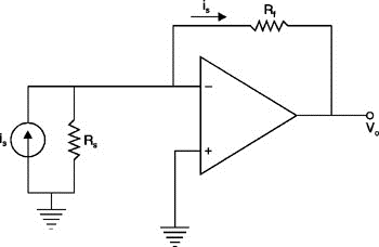
A transresistance amplifier (TRA) is an electronic device that converts an input current into an output voltage. The TRA is often referred to as a transimpedance amplifier. Here are some key features of transresistance amplifiers:
Applications
Transresistance amplifiers are used in a variety of applications, including current-to-voltage converters, photodiode amplifiers, and current sensing circuits. These applications exploit the fact that the transresistance gain is a function of the feedback resistance. Transresistance amplifiers are also used in operational amplifiers, which are used in many analog signal processing applications.
Advantages
One of the main advantages of transresistance amplifiers is that they provide a high output voltage, which makes them useful for driving loads such as operational amplifiers and analog-to-digital converters. Additionally, transresistance amplifiers can be designed to provide high accuracy, which reduces errors in measurement applications.
Disadvantages
One of the main disadvantages of transresistance amplifiers is that they can introduce noise and distortion into a signal. Additionally, transresistance amplifiers can be sensitive to temperature changes and other environmental factors, which can affect their performance.
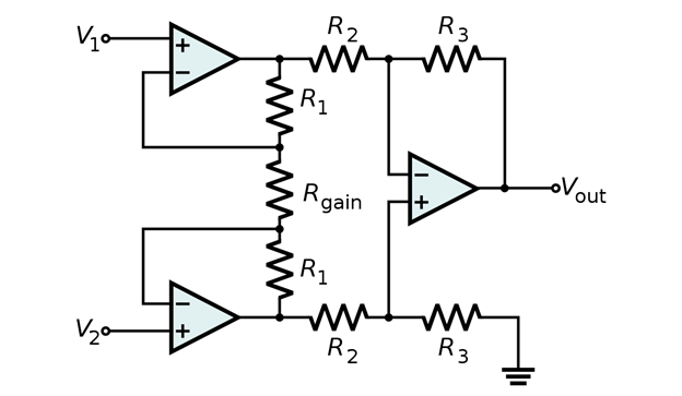
Instrument Amplifiers
An instrumentation amplifier is an electronic device that amplifies a small signal from a transducer to a level that is suitable for further processing. Instrumentation amplifiers are used in a wide range of applications, including medical equipment, industrial control systems, and scientific instruments. Here are some key features of instrumentation amplifiers:
Applications
Instrumentation amplifiers are used in a variety of applications, including medical equipment, industrial control systems, and scientific instruments. These applications exploit the fact that instrumentation amplifiers can amplify small signals from transducers, which are used to measure physical quantities such as temperature, pressure, and strain.
Advantages
One of the main advantages of instrumentation amplifiers is that they provide high gain and high input impedance, which makes them useful for amplifying small signals from transducers. Additionally, instrumentation amplifiers can be designed to provide high accuracy, which reduces errors in measurement applications.
Disadvantages
One of the main disadvantages of instrumentation amplifiers is that they can introduce noise and distortion into a signal. Additionally, instrumentation amplifiers can be sensitive to temperature changes and other environmental factors, which can affect their performance.
Design Considerations
When designing an instrumentation amplifier, several factors must be considered, including:
- Gain: The gain of the instrumentation amplifier must be high enough to amplify the small signal from the transducer to a level that is suitable for further processing.
- Input Impedance: The input impedance of the instrumentation amplifier must be high enough to avoid loading the transducer and affecting its performance.
- Common-Mode Rejection Ratio (CMRR): The CMRR of the instrumentation amplifier must be high enough to reject common-mode noise and interference.
- Bandwidth: The bandwidth of the instrumentation amplifier must be wide enough to avoid distortion and phase shift in the amplified signal.
Overall, instrumentation amplifiers are a fundamental component in many electronic devices, providing high gain and accuracy for a wide range of applications. They are commonly used in feedback loops, and there are several different types of instrumentation amplifiers available to suit different applications.
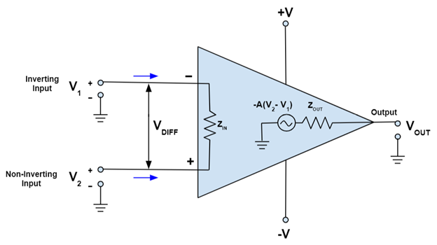
Operational Amplifiers (Op-Amps)
Operational Amplifiers, also known as Op-Amps, are voltage amplifying devices designed to be used with components like capacitors and resistors, between its in/out terminals. They are essentially a core part of analog devices. Feedback components like these are used to determine the operation of the amplifier. The amplifier can perform many different operations (resistive, capacitive, or both), giving it the name Operational Amplifier.
Applications
Op-Amps are used in a wide range of applications, including audio and video applications, voltage regulators, medical equipment, industrial control systems, and scientific instruments. Op-Amps are commonly available as integrated circuits (ICs). They have input and output terminals capable of giving out a larger version of voltage signals that are being passed through them. They can be designed to act as a voltage amplifying device when used with active components such as transistors and passive components like resistors and capacitors to provide the desired response.
Advantages
One of the main advantages of Op-Amps is that they are linear devices that are ideal for DC amplification and are used often in signal conditioning, filtering, or other mathematical operations (add, subtract, integration, and differentiation). With only a handful of external components, it can be made to perform a wide variety of analog signal-processing tasks. It is also quite affordable, with most general-purpose amplifiers selling for under a dollar.
Disadvantages
One of the main disadvantages of Op-Amps is that they can introduce noise and distortion into a signal. Additionally, Op-Amps can be sensitive to temperature changes and other environmental factors, which can affect their performance.
Design Considerations
When designing an Op-Amp circuit, several factors must be considered, including:
- Gain: The gain of the Op-Amp must be high enough to amplify the signal to a level that is suitable for further processing.
- Input Impedance: The input impedance of the Op-Amp must be high enough to avoid loading the source and affecting its performance.
- Output Impedance: The output impedance of the Op-Amp must be low enough to avoid loading the load and affecting its performance.
- Bandwidth: The bandwidth of the Op-Amp must be wide enough to avoid distortion and phase shift in the amplified signal.
Overall, Op-Amps are a fundamental component in many electronic devices, providing high gain and accuracy for a wide range of applications. They are commonly used in feedback loops, and there are several different types of Op-Amps available to suit different applications.
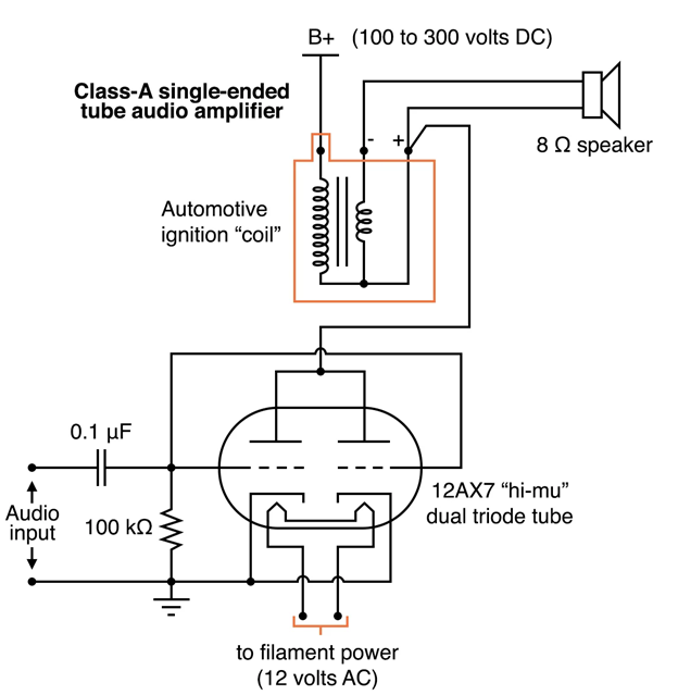
Valve (or) Vacuum Tube Amplifiers
Valve Amplifiers, also known as Vacuum Tube Amplifiers, are electronic devices that use vacuum tubes to amplify the amplitude or power of a signal. They are a core part of analog devices and have been used in a wide range of applications, including audio and video applications, voltage regulators, medical equipment, industrial control systems, and scientific instruments. Here are some key features of valve amplifiers:
History
Valve amplifiers have been around since the early 1900s. In 1906, the inventor and radio pioneer Lee De Forest created the first electronic amplifying device, the triode which he named the Audion. In the 1950s and 60s, most vacuum tubes were replaced by transistors in the west. In the 70s and 80s, tubes saw continued use in amplifiers and oscillators as they were more reliable at high power levels. Today, vacuum tubes are still used in some applications, particularly in audio amplifiers.
Applications
Valve amplifiers are commonly used in audio applications, particularly in guitar amplifiers, as many professional guitar players use tube amps because of their renowned ‘tone’. They are also used in satellite transponders such as DirecTV and GPS, high-quality stereo amplifiers, military applications (such as radar), and very high-power radio and UHF television transmitters.
Advantages
One of the main advantages of valve amplifiers is that they produce a different and desirable sound, often referred to as “tube tone”. Most audio technicians and scientists theorize that the “even harmonic distortion” produced by valve tubes sounds more pleasing to the ear than transistors, regardless of style. Valve amplifiers are also known for their high headroom, which allows them to handle sudden peaks in sound without distortion.
Disadvantages
One of the main disadvantages of valve amplifiers is that they are less efficient than solid-state amplifiers, which means they produce more heat and consume more power. Additionally, valve amplifiers are more expensive and require more maintenance than solid-state amplifiers.
Design Considerations
When designing a valve amplifier circuit, several factors must be considered, including:
- Gain: The gain of the valve amplifier must be high enough to amplify the signal to a level that is suitable for further processing.
- Input Impedance: The input impedance of the valve amplifier must be high enough to avoid loading the source and affecting its performance.
- Output Impedance: The output impedance of the valve amplifier must be low enough to avoid loading the load and affecting its performance.
- Biasing: The biasing of the valve amplifier must be set correctly to ensure proper operation and prevent damage to the tubes.
Overall, valve amplifiers are a fundamental component in many electronic devices, providing a unique sound and high headroom for a wide range of applications. They are commonly used in audio applications, particularly in guitar amplifiers, and there are several different types of valve amplifiers available to suit different applications.
Distributed Amplifiers
Distributed Amplifiers are a type of amplifier that incorporates transmission line theory into traditional amplifier design to obtain a larger gain-bandwidth product than is realizable by conventional circuits. Here are some key features of distributed amplifiers:
History
The design of distributed amplifiers was first formulated by William S. Percival in 1936. In that year, Percival proposed a design by which the transconductances of individual vacuum tubes could be added linearly without lumping their element capacitances at the input and output, thus arriving at a circuit that achieved a gain-bandwidth product greater than that of an individual tube. Percival’s design did not gain widespread awareness, however, until a publication on the subject was authored by Ginzton, Hewlett, Jasberg, and Noe in 1948. It is to this later paper that the term distributed amplifier can actually be traced.
Applications
Distributed amplifiers are used in a wide range of applications, including RF and microwave transmission systems, satellite communications, radar systems, and wireless communication systems. They are particularly useful in applications where a larger bandwidth is needed.
Advantages
One of the main advantages of distributed amplifiers is that they provide a larger gain-bandwidth product than is realizable by conventional circuits. Additionally, distributed amplifiers can be designed to provide high efficiency, which reduces power consumption and heat dissipation.
Disadvantages
One of the main disadvantages of distributed amplifiers is that they can introduce noise and distortion into a signal. Additionally, distributed amplifiers can be sensitive to temperature changes and other environmental factors, which can affect their performance.
Design Considerations
When designing a distributed amplifier circuit, several factors must be considered, including:
- Gain: The gain of the distributed amplifier must be high enough to amplify the signal to a level that is suitable for further processing.
- Input Impedance: The input impedance of the distributed amplifier must be high enough to avoid loading the source and affecting its performance.
- Output Impedance: The output impedance of the distributed amplifier must be low enough to avoid loading the load and affecting its performance.
- Bandwidth: The bandwidth of the distributed amplifier must be wide enough to avoid distortion and phase shift in the amplified signal.
Overall, distributed amplifiers are a fundamental component in many electronic devices, providing high gain and efficiency for a wide range of applications. They are commonly used in feedback loops, and there are several different types of distributed amplifiers available to suit different applications.

Conclusion
In conclusion, amplifiers are a fundamental component in many electronic devices, providing high gain and accuracy for a wide range of applications. There are different types of amplifiers, each with its own advantages and disadvantages. The most well-known types of amplifiers include voltage-controlled amplifiers, current-controlled amplifiers, power amplifiers, transconductance amplifiers, transresistance amplifiers, instrumentation amplifiers, valve amplifiers, and distributed amplifiers. Power amplifiers are often confused as the only categories of amplifiers, but they are actually types of power amplifiers and are classified on the basis of the proportion of the input cycle during which the amplifier is giving an output. Amplifiers have a lot of parameters and conditions in the real world, and amplification is never perfectly efficient. However, with proper design considerations, amplifiers can be optimized for specific applications.
FAQs about Types of Amplifiers
- What are the different types of amplifiers?
There are different types of amplifiers, including voltage-controlled amplifiers, current-controlled amplifiers, power amplifiers, transconductance amplifiers, transresistance amplifiers, instrumentation amplifiers, valve amplifiers, and distributed amplifiers.
- What are the advantages of valve amplifiers?
Valve amplifiers produce a different and desirable sound, often referred to as “tube tone”. They are also known for their high headroom, which allows them to handle sudden peaks in sound without distortion.
- What are the disadvantages of distributed amplifiers?
Distributed amplifiers can introduce noise and distortion into a signal. Additionally, they can be sensitive to temperature changes and other environmental factors, which can affect their performance.
- What are the different classes of power amplifiers?
The different classes of power amplifiers include A, B, AB, C, D, E, F, and T. Each class has its own advantages and disadvantages.
- What are the design considerations when designing an amplifier circuit?
When designing an amplifier circuit, several factors must be considered, including gain, input impedance, output impedance, and bandwidth. These factors are critical to ensure proper operation and prevent damage to the amplifier.