Flip-flops are digital electronic circuits that are used to store binary data in two stable states. They are the fundamental building blocks of all memory devices and are widely used in computers, communications, and many other types of systems. There are four basic types of flip-flops: SR (set-reset), D (data or delay), T (toggle), and JK. Each type of flip-flop has its own unique features and benefits, making them suitable for different applications. In this article, we will explore the different types of electric flip-flops in detail. We will discuss their characteristics, truth tables, and applications. We will also explain the differences between latches and flip-flops and how they are used in digital circuits. So, let’s dive in and explore the world of electric flip-flops!
What are Flip-Flops?
Flip-flops are digital electronic circuits that can store binary data in two stable states. They are the fundamental building blocks of all memory devices and are widely used in computers, communications, and many other types of systems. There are four basic types of flip-flops: SR (set-reset), D (data or delay), T (toggle), and JK. The behavior of each type can be described by its characteristic equation, which derives the next output in terms of the input signal(s) and/or the current output. The output of a flip-flop is controlled by its previous and current inputs, but the change in output only happens at precise times set by the clock input.
Types of Flip-Flops
The types of flip-flops are as follows:
- SR Flip-Flop
- D Flip-Flop
- JK Flip-Flop
- T Flip-Flop
Each type of flip-flop has its own unique features and benefits, making them suitable for different applications. For example, the D flip-flop is generally used for shift-registers and counters, while the T flip-flop is a simplified version of the JK flip-flop. In the next sections, we will explore each type of flip-flop in more detail and discuss their characteristics, truth tables, and applications.
SR Flip-Flop
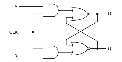
The SR flip-flop, also known as the Set-Reset flip-flop, is a 1-bit memory bistable device that has two inputs: SET and RESET. The SET input ‘S’ sets the device or produces the output 1, while the RESET input ‘R’ resets the device or produces the output 0. The SET and RESET inputs are labeled as S and R, respectively. The SR flip-flop is the simplest type of flip-flop and can be constructed using two cross-coupled NAND gates or NOR gates. The term “flip-flop” relates to the actual operation of the device, as it can be “flipped” to a logic set state or “flopped” back to the opposing logic reset state. The SR flip-flop is a controlled bi-stable latch where the clock signal is the control signal. The output of the SR flip-flop depends on the set and reset conditions, which is either at the logic level “0” or “1”. The memory size of the SR flip-flop is one bit. The truth table of the SR flip-flop is as follows:
- S=0, R=0: No change
- S=0, R=1: Reset (Q=0, Q’=1)
- S=1, R=0: Set (Q=1, Q’=0)
- S=1, R=1: Invalid state (Q=Q’=X)
Applications of the SR flip-flop include:
- As a memory element in digital circuits
- As a building block for other types of flip-flops
- In counters and shift registers
- In control circuits and alarms
The SR flip-flop is the basic building block of all other flip-flops, and its characteristics are used to design more complex circuits. The SR flip-flop is easy to understand and implement, making it a popular choice for simple digital circuits. However, it has some limitations, such as the possibility of entering an invalid state when both inputs are high. To overcome this limitation, other types of flip-flops, such as the JK and D flip-flops, were developed.
D Flip-Flop
The D flip-flop, also known as the Delay flip-flop, is a digital circuit that is used to store a single bit of binary information. It has a single input, known as the “data” input, labeled as “D”. The D flip-flop is clocked, meaning it only stores data on the rising or falling edge of the clock signal, often labeled as C or CLK, and it retains its value until the next rising edge. This means that it doesn’t have the same problem with forbidden states as regular flip-flops. The data input determines the state that the flip-flop will store. When the clock input is activated and changes from 0 to 1, the flip-flop stores the state of the data input as its output. This means that the D flip-flop “latches” onto the input value and holds it until the next clock cycle. The D flip-flop is a modified form of an RS clocked flip-flop and can be designed using a combinational circuit with feedback and a clock. The D flip-flop is used in many sequential circuits as a register, counter, etc. The truth table for the D flip-flop is shown below:
- D=0: No change
- D=1: Data stored
Applications of the D flip-flop include:
- As a memory element in digital circuits
- As a building block for other types of flip-flops
- In counters and shift registers
- In control circuits and alarms
The D flip-flop is widely used in digital electronics and computing because of its simplicity and versatility. It is a fundamental sequential circuit element that can store one bit at a time. The D flip-flop is also used in many other applications, such as in divide-by-two circuits, where the output changes state at half the frequency of the clock signal. The D flip-flop is a crucial component in digital circuits and is used in many applications where data storage is required.
JK Flip-Flop
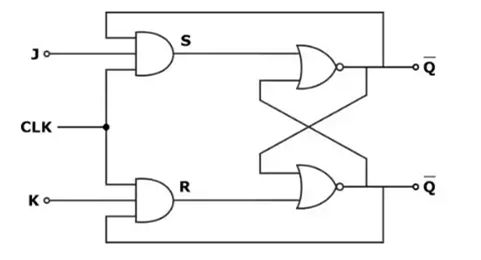
The JK flip-flop is a type of digital circuit that is widely used in digital electronics. It is considered to be a universal flip-flop circuit and is an improvement on the SR flip-flop. The JK flip-flop has two inputs, J and K, and a clock input. The J and K inputs are used to set or reset the flip-flop, depending on the state of the clock input. The JK flip-flop is a gated SR flip-flop with the addition of a clock input circuitry. The invalid or illegal output condition occurs when both of the inputs are set to 1 and are prevented by the addition of a clock. The JK flip-flop is a modification of the SR flip-flop, where S=R=1 is not a problem. The input condition of J=K=1 gives an output inverting the output state. However, the outputs are the same when one tests the circuit practically. If J and K data input are different (i.e. high and low), then the output Q takes the value of J at the next clock edge. If J and K are both low, then no change occurs. If J and K are both high at the clock edge, then the output will toggle from one state to the other. JK Flip-Flops can function as Set or Reset Flip-flops. The truth table for the JK flip-flop is shown below:
- J=0, K=0: No change
- J=0, K=1: Reset (Q=0, Q’=1)
- J=1, K=0: Set (Q=1, Q’=0)
- J=1, K=1: Toggle (Q’=Q’)
Applications of the JK flip-flop include:
- As a memory element in digital circuits
- As a building block for other types of flip-flops
- In counters and shift registers
- In control circuits and alarms
The JK flip-flop is a versatile and widely used digital circuit that is used in many applications where data storage is required. It is a fundamental sequential circuit element that can store one bit at a time. The JK flip-flop is also used in many other applications, such as in divide-by-two circuits, where the output changes state at half the frequency of the clock signal.
T Flip-Flop
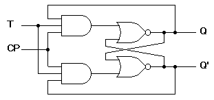
The T flip-flop, also known as the Toggle flip-flop, is a single input digital circuit that holds or toggles its output according to the input state. Toggling means changing the next state output to complement the current state. T is an abbreviation for Toggle. The T flip-flop has one Toggle input (T) and one clock signal input (CLK). The T flip-flop is similar to the JK flip-flop, but it has only one external input along with a clock. The T flip-flop can be positive or negative edge-triggered. In other words, the inputs will affect the output only when the clock signal changes from low to high for positive, or from high to low for negative. When an edge is applied to the clock input, the flip-flop will hold or latch the last output (Q) if T=0, and will toggle it to its complement if T=1. The T flip-flop can be designed using a D flip-flop with the input connected to both the D and the clock inputs through an XOR gate. The truth table for the T flip-flop is as follows:
- T=0: No change
- T=1: Toggle
Applications of the T flip-flop include:
- As a memory element in digital circuits
- In frequency synthesizers and frequency multiplication circuits
- In counters and shift registers
The T flip-flop is a simple and versatile digital circuit that is used in many applications where data storage is required. It is a fundamental sequential circuit element that can store one bit at a time. The T flip-flop is also used in many other applications, such as in divide-by-two circuits, where the output changes state at half the frequency of the clock signal. The T flip-flop is a crucial component in digital circuits and is used in many applications where data storage is required.
Application of Flip-Flops
Flip-flops are essential building blocks of digital electronic systems used in computers, communications, and many other types of systems. They are used as data storage elements and are the basic storage element in sequential logic. Flip-flops are used in many applications where data storage is required. Here are some of the applications of flip-flops:
- Counters and Shift Registers: Flip-flops are used in counters and shift registers to store and manipulate data. Counters are used to count the number of clock pulses, while shift registers are used to store and shift data.
- Input Synchronization: Flip-flops are used to synchronize variably-timed input signals to some reference timing signal. This is useful in applications where data needs to be synchronized before processing.
- Frequency Multiplication: The T flip-flop can be used to multiply the frequency of a clock signal by two, making it useful in applications such as frequency synthesizers and frequency multiplication circuits.
- Control Circuits and Alarms: Flip-flops are used in control circuits and alarms to store and manipulate data. They are used to control the operation of various devices and to trigger alarms when certain conditions are met.
- Memory Elements: Flip-flops are used as memory elements in digital circuits. They are used to store data in registers and to hold data in memory.
In conclusion, flip-flops are fundamental building blocks of digital electronic systems used in computers, communications, and many other types of systems. They are used as data storage elements and are the basic storage element in sequential logic. Flip-flops are used in many applications where data storage is required, including counters and shift registers, input synchronization, frequency multiplication, control circuits and alarms, and memory elements.
Conclusion
In conclusion, flip-flops are an essential component of digital electronic systems used in computers, communications, and many other types of systems. There are four basic types of flip-flops: SR, D, JK, and T. Each type of flip-flop has its own unique features and benefits, making them suitable for different applications. While SR and D flip-flops are the most commonly used, JK and T flip-flops feature more functionality. Flip-flops are used in many applications where data storage is required, including counters and shift registers, input synchronization, frequency multiplication, control circuits and alarms, and memory elements. Whether you’re looking for a basic flip-flop or a more advanced one, there is a type of flip-flop that will meet your needs. So, whether you’re building a digital circuit or just looking for a comfortable pair of flip-flops to wear in the summer, understanding the different types of flip-flops is essential.
FAQs about Types of Flip Flops
- What are the four main types of flip-flops?
The four main types of flip-flops are SR, D, JK, and T.
- What is the difference between a latch and a flip-flop?
A latch is a circuit with two stable states that can be changed by applying varying inputs, while a flip-flop is a circuit with two stable states that can store binary data and can be changed by applying varying inputs.
- What is a T flip-flop?
A T flip-flop is a type of flip-flop that has only one input, along with a clock input. It is called a toggle flip-flop because of its ability to complement its state.
- What is the truth table for a D flip-flop?
| D | Q | Q (t+1) |
|---|---|---|
| 0 | 0 | 0 |
| 1 | 0 | 1 |
| 0 | 1 | 0 |
| 1 | 1 | 1 |
The truth table above shows the relationship between the input (D) and the output (Q) of a D flip-flop. The output (Q) changes only when there is an edge of the clock signal. The T flip-flop is a simplified version of the JK flip-flop and has only one input. Flip-flops are used in many applications where data storage is required, including counters and shift registers, input synchronization, frequency multiplication, control circuits and alarms, and memory elements. Understanding the different types of flip-flops and their applications is essential for anyone working with digital circuits.
- What are the applications of flip-flops?
Flip-flops are used in many applications where data storage is required, including counters and shift registers, input synchronization, frequency multiplication, control circuits and alarms, and memory elements.