In the world of electronics, logic forms the backbone that enables the functioning of complex systems and devices. Logic encompasses the principles and rules that govern the flow of information and decision-making within electronic circuits. Understanding the different types of logics is essential for engineers, technicians, and enthusiasts, as it serves as the foundation for designing, analyzing, and troubleshooting electronic systems.
From the basic building blocks of digital circuits to advanced microprocessors, various types of logics are used to process and manipulate binary data. This article provides an overview of the different types of logics commonly encountered in electronics, exploring their principles, characteristics, and diverse applications.
We’ll begin with foundational logic gates such as AND, OR, and NOT, and expand to more advanced types like XOR, NAND, and NOR gates. Furthermore, we’ll discuss sequential logic, combinational logic, and programmable logic devices, which play critical roles in Data and Control Systems. These logic types are pivotal in enabling functionality in components such as types of latches and types of comparators.
In addition, we’ll touch on related concepts like types of memory and types of codecs in electronics, highlighting their interplay with logic systems to create efficient and versatile designs. Whether you are a beginner eager to grasp the basics or a seasoned professional looking to refine your expertise, this guide offers insights into how logic types drive modern technology.
By the end of this exploration, you will have a comprehensive understanding of the various types of logics in electronics. Armed with this knowledge, you’ll be empowered to analyze circuits, troubleshoot issues, and innovate solutions that push the boundaries of technology. Let’s embark on this journey through logic types and uncover the fascinating world of electronics and data-driven systems!
Different Types of Logic
Here is a list of types of logics commonly used in electronics:
- Basic Logic Gates: These are the fundamental building blocks of digital circuits and include logic gates such as AND, OR, NOT, NAND, NOR, and XOR. They manipulate binary signals (0s and 1s) based on specific logic rules.
- Combinational Logic: Combinational logic circuits process input signals and produce output signals solely based on their current inputs. They don’t have any memory elements, making them suitable for applications where the output depends only on the current input conditions.
- Sequential Logic: Sequential logic circuits have memory elements and utilize the concept of feedback to store information and produce outputs based on both current and past inputs. Flip-flops and registers are commonly used sequential logic components.
- Programmable Logic Devices (PLDs): PLDs are integrated circuits that can be programmed to implement custom digital logic functions. They provide flexibility and can be reprogrammed multiple times, making them versatile for a variety of applications.
- Multiplexers and Demultiplexers: Multiplexers (MUX) are used to select one of many input signals and route it to a single output, based on control signals. Demultiplexers (DEMUX) perform the opposite function, routing a single input signal to one of many outputs.
- Decoders and Encoders: Decoders convert binary input signals into a specific set of output signals, often used for addressing purposes. Encoders perform the reverse operation, encoding multiple input signals into a smaller number of output signals.
- Arithmetic Logic Units (ALUs): ALUs are digital circuits responsible for performing arithmetic and logical operations, such as addition, subtraction, multiplication, division, and comparison. They are crucial components of microprocessors and calculators.
- Memory Units: Memory units, such as Random Access Memory (RAM) and Read-Only Memory (ROM), store and retrieve digital data in electronic systems. They play a vital role in data storage, temporary storage (volatile memory), and permanent storage (non-volatile memory).
- Programmable Logic Controllers (PLCs): PLCs are specialized digital computers used for industrial automation and control systems. They incorporate various types of logics and are programmed to monitor and control processes and machinery.
- Finite State Machines (FSMs): FSMs are models used to represent systems with discrete states and transition between these states based on inputs. They find applications in control systems, digital design, and communication protocols.
These are just a few examples of the types of logics used in electronics. Each type has its unique characteristics, applications, and significance in digital circuit design and electronic systems. Understanding these logics is essential for anyone working with electronic devices and circuits.
Basic Logic Gates
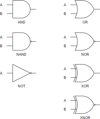
Logic gates are the fundamental building blocks of digital circuits, responsible for performing logical operations on binary inputs to produce binary outputs. There are several types of basic logic gates, each with its unique behavior and truth table. Let’s explore some of the most common ones:
AND Gate
The AND gate is a fundamental logic gate that produces an output of 1 only when all its inputs are 1. It follows the logic that if all inputs are true, the output is true; otherwise, the output is false. The symbol for an AND gate is typically represented as an intersection or dot.
OR Gate
The OR gate is another essential logic gate that generates an output of 1 if any of its inputs are 1. It adheres to the logic that if any input is true, the output is true. The symbol for an OR gate is usually represented as a plus sign (+) or a curved shape.
NOT Gate
The NOT gate, also known as an inverter, produces the logical complement of its input. In other words, it reverses the input signal. If the input is 1, the output is 0, and vice versa. The symbol for a NOT gate is usually represented as a triangle pointing to the right with a small circle at its input.
NAND Gate
The NAND gate is a combination of an AND gate followed by a NOT gate. It produces an output of 0 only when all inputs are 1; otherwise, the output is 1. In essence, it is an inverted AND gate. The symbol for a NAND gate is typically represented as an AND gate with a small circle at its output.
NOR Gate
The NOR gate is a combination of an OR gate followed by a NOT gate. It generates an output of 1 only when all inputs are 0; otherwise, the output is 0. It is essentially an inverted OR gate. The symbol for a NOR gate is usually represented as an OR gate with a small circle at its output.
XOR Gate
The XOR gate, short for Exclusive OR gate, produces an output of 1 if the number of inputs that are 1 is odd. If the number of inputs that are 1 is even, the output is 0. XOR gates are commonly used in arithmetic and error detection circuits. The symbol for an XOR gate is usually represented as a plus sign enclosed within a circle.
Understanding these basic logic gates and their behavior is crucial for designing and analyzing digital circuits. By combining these gates and their outputs, complex logical operations can be achieved, forming the foundation for advanced digital systems and electronic devices.
Combinational Logic
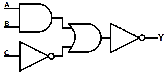
Combinational logic refers to a type of digital logic design in which the output depends solely on the current input values. It consists of logic gates interconnected to produce specific logical functions without any memory elements. Combinational logic circuits are widely used in digital systems where the output is determined by the combination of inputs at any given instant. Let’s explore the key aspects of combinational logic:
Definition and Characteristics
Combinational logic circuits are designed to perform logic operations and produce output signals based solely on the current input values. They don’t have any internal memory elements, making them suitable for applications where the output depends only on the immediate input conditions. The behavior of combinational logic circuits is defined by truth tables, which specify the output for every possible combination of input values.
Logic Gates in Combinational Logic
Combinational logic circuits are constructed using basic logic gates such as AND, OR, NOT, NAND, NOR, and XOR gates. These gates are interconnected in various configurations to achieve the desired logical functions. By combining different gates and their outputs, complex logical operations can be implemented.
Boolean Algebra and Simplification
Boolean algebra provides a mathematical framework for analyzing and simplifying combinational logic circuits. By applying Boolean laws and theorems, expressions and equations representing the logic functions can be simplified, resulting in optimized circuit designs. Boolean algebra operations, such as AND, OR, and NOT, are used to manipulate and simplify the expressions.
Designing Combinational Logic Circuits
The process of designing combinational logic circuits involves several steps, including understanding the problem requirements, defining the truth table, creating logical expressions or equations, simplifying the expressions, and implementing the final circuit using appropriate logic gates. Various techniques, such as Karnaugh maps or Boolean algebra manipulations, can aid in the design process.
Applications of Combinational Logic
Combinational logic circuits find applications in various digital systems and electronic devices. They are used in arithmetic circuits, multiplexers, demultiplexers, decoders, encoders, and more. Combinational logic is also vital in control systems, data processing, digital signal processing, and computer architecture.
Testing and Verification
Testing and verification are crucial steps in the design and implementation of combinational logic circuits. Techniques such as simulation, truth table analysis, and test pattern generation are employed to ensure the correctness and functionality of the circuit. Fault detection and correction methods are used to identify and rectify any potential errors.
Combinational logic plays a significant role in the design and operation of digital systems, enabling complex logical operations and data manipulation. By understanding the principles and techniques involved, engineers and designers can create efficient and reliable combinational logic circuits to meet the requirements of various applications.
Sequential Logic
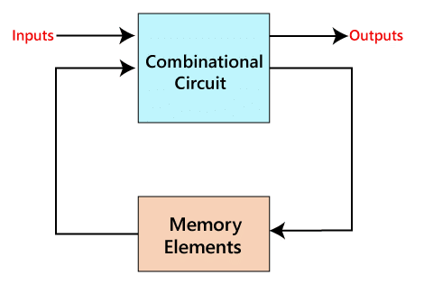
Sequential logic is a type of digital logic design in which the output not only depends on the current input values but also on the past history of inputs and the internal state of the circuit. Unlike combinational logic, sequential logic circuits incorporate memory elements, enabling them to store and remember information. Let’s explore the key aspects of sequential logic:
Definition and Characteristics
Sequential logic circuits are designed to perform logic operations and produce output signals based on both the current input values and the previous state of the circuit. They incorporate memory elements, typically in the form of flip-flops or registers, which store information and enable the circuit to retain and recall past inputs. The output of a sequential logic circuit is determined by the combination of current inputs and the stored state.
Flip-Flops and Registers
Flip-flops are fundamental components of sequential logic circuits. They can store a single bit of information, which can be either 0 or 1. Flip-flops have two stable states, commonly referred to as “0” and “1,” and can transition from one state to another based on clock signals or specific triggering conditions. Registers are a collection of flip-flops used to store multiple bits of information simultaneously.
State Diagrams and State Tables
Sequential logic circuits can be represented using state diagrams and state tables. A state diagram illustrates the various states of the circuit and the transitions between them based on inputs and clock signals. State tables provide a concise representation of the circuit’s behavior, indicating the current state, input conditions, next state, and output values.
Synchronous and Asynchronous Sequential Logic
Sequential logic circuits can be categorized into two types: synchronous and asynchronous. In synchronous sequential logic, the circuit’s operation is synchronized with a common clock signal, ensuring that all state transitions occur simultaneously. Asynchronous sequential logic, on the other hand, operates without a clock signal and relies on specific triggering conditions for state transitions.
Finite State Machines (FSMs)
Finite State Machines (FSMs) are models used to represent and analyze sequential logic circuits. They consist of a finite number of states, inputs, outputs, and transition rules. FSMs provide a structured approach to designing and understanding complex sequential logic circuits, facilitating the identification of states, transitions, and output behaviors.
Applications of Sequential Logic
Sequential logic circuits are extensively used in various applications, including memory units, counters, shift registers, control units, and microprocessors. They play a crucial role in enabling sequential operations, data storage, and complex control functions in digital systems.
Understanding sequential logic is essential for designing and analyzing digital circuits that require memory, historical data, and dynamic behavior. By utilizing flip-flops, state diagrams, and FSMs, engineers, and designers can create sophisticated sequential logic circuits that fulfill the requirements of a wide range of applications.
Programmable Logic Devices (PLDs)
Programmable Logic Devices (PLDs) are integrated circuits that can be programmed to implement custom digital logic functions. They provide flexibility and versatility in digital circuit design by allowing engineers to define the desired logic functions and interconnections within the device. Let’s explore the key aspects of Programmable Logic Devices:
PLDs are widely used in digital systems and electronic designs, offering a cost-effective and efficient alternative to custom-built logic circuits. They are programmable by the user, enabling the implementation of various logic functions, such as combinational and sequential logic, arithmetic operations, data processing, and control functions.
Types of PLDs
There are several types of PLDs available, each with its own programming method and architecture. The three main types of PLDs are:
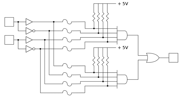
- Programmable Logic Arrays (PLAs): PLAs consist of an array of AND gates followed by an array of OR gates. The interconnection between the inputs and gates can be programmed to define the desired logic functions.
- Programmable Array Logic (PAL): PAL devices feature an array of programmable AND gates and a fixed OR gate array. The AND gates can be programmed, while the OR connections are fixed.
- Field-Programmable Gate Arrays (FPGAs): FPGAs are highly versatile PLDs that contain a vast number of configurable logic blocks (CLBs) interconnected through programmable routing resources. FPGAs offer extensive flexibility and are capable of implementing complex digital systems.
Programming Methods
PLDs can be programmed using different methods, depending on the type of device. Some common programming methods include:
- Fuse Programming: In this method, the programming information is permanently stored by blowing fuses or antifuses within the PLD.
- One-Time Programmable (OTP): OTP PLDs allow programming through a non-reversible process, typically using electrically programmable read-only memory (EPROM) technology.
- Electrically Erasable Programmable Read-Only Memory (EEPROM): Some PLDs utilize EEPROM technology, allowing for reprogramming by electrically erasing and rewriting the configuration data.
- In-System Programming (ISP): With ISP, the PLD can be programmed or reprogrammed directly in the target system, eliminating the need for physical removal and replacement of the device.
Benefits and Applications
PLDs offer several benefits in digital circuit design and implementation. These include:
- Flexibility: PLDs allow for quick prototyping and iteration, as the logic functions can be easily reprogrammed or modified to accommodate design changes.
- Cost and Time Efficiency: PLDs eliminate the need for custom-built logic circuits, reducing development time and costs associated with hardware redesign.
- Design Optimization: PLDs enable designers to create highly optimized and efficient logic functions by tailoring the configuration to match specific application requirements.
PLDs find applications in a wide range of industries, including telecommunications, automotive, aerospace, consumer electronics, industrial automation, and more. They are used in various systems, such as data processing, signal processing, control units, memory interfaces, and complex digital designs.
Understanding PLDs and their programming capabilities empowers engineers and designers to implement customized logic functions and rapidly prototype digital systems while maintaining flexibility and cost efficiency.
Multiplexers and Demultiplexers
Multiplexers and demultiplexers are essential components in digital circuits that facilitate the efficient transmission and routing of multiple signals over a shared channel or bus. They play a crucial role in data selection, signal routing, and communication systems. Let’s explore the key aspects of multiplexers and demultiplexers:
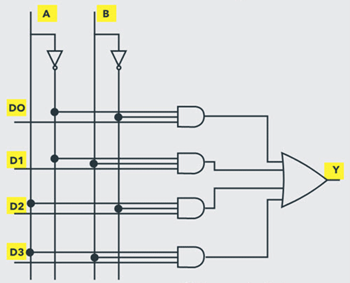
A multiplexer, commonly referred to as a “MUX,” is a digital circuit that allows multiple input signals to be transmitted through a single output line based on select control signals. It effectively combines several input lines into a single output line. Multiplexers are widely used in various applications, such as data transmission, analog-to-digital conversion, and communication systems.
Operation and Symbol
A multiplexer consists of multiple data inputs, a select input, and a single output. The select input determines which data input is transmitted to the output. The number of data inputs and select lines in a multiplexer depends on its configuration. Multiplexers are commonly represented by a trapezoid-shaped symbol, with the data inputs on one side, the select inputs on the other side, and the output at the narrower end.
Applications
Multiplexers are utilized in various applications, including:
- Data Multiplexing: Multiplexers enable the transmission of multiple data streams over a single communication channel, optimizing bandwidth usage.
- Analog-to-Digital Conversion: Multiplexers are used to select and route analog input signals to an analog-to-digital converter (ADC) for conversion into digital signals.
- Memory Addressing: In computer systems, multiplexers are employed for memory addressing, allowing the selection of specific memory locations.
Introduction to Demultiplexers
A demultiplexer, commonly referred to as a “DEMUX,” is a digital circuit that performs the reverse operation of a multiplexer. It takes a single input and transmits it to one of several possible outputs based on select control signals. Demultiplexers are used to route signals from a common input line to specific output lines, enabling data distribution and signal routing.
Operation and Symbol
A demultiplexer consists of a single input, select inputs, and multiple output lines. The selected inputs determine which output line receives the input signal. Demultiplexers are typically represented by a shape similar to a multiplexer but with a narrow end at the input and the data outputs branching out.
Applications
Demultiplexers find applications in various scenarios, including:
- Signal Routing: Demultiplexers allow for the distribution of a single input signal to multiple output channels, enabling efficient signal routing and distribution.
- Display Systems: Demultiplexers are used in multiplexed display systems, where a single set of control lines is used to drive multiple display segments.
- Memory Decoding: Demultiplexers assist in memory decoding, where a single address input is routed to a specific memory location.
Understanding the operation and applications of multiplexers and demultiplexers is crucial in digital circuit design, data transmission, and communication systems. By utilizing these components effectively, engineers can optimize data routing, reduce hardware complexity, and enhance overall system performance.
Decoders and Encoders
Decoders and encoders are essential components in digital circuits that are used for data manipulation, signal routing, and address decoding. They serve distinct purposes in converting data between different representations. Let’s explore the key aspects of decoders and encoders:
Introduction to Decoders
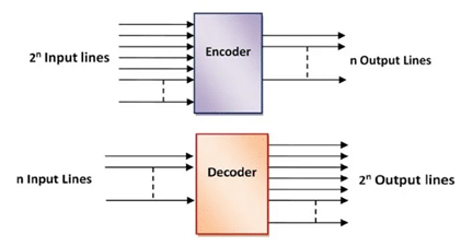
Decoders are digital circuits that convert coded inputs into a set of output signals, typically based on a binary code. They are primarily used for address decoding, where a specific input code is translated into an active output line or combination of output lines. Decoders can have multiple inputs and outputs, and the number of outputs is determined by the binary code’s complexity.
Operation and Symbol
A decoder consists of multiple inputs and outputs, with each output representing a specific combination of input values. When a particular input combination matches the decoder’s internal logic, the corresponding output line(s) are activated. Decoders are usually represented by a rectangular shape with the inputs on one side and the outputs on the other side.
Applications
Decoders find applications in various scenarios, including:
- Memory Address Decoding: Decoders are commonly used in memory systems to select specific memory locations based on the address inputs.
- Display Systems: In multiplexed display systems, decoders are utilized to activate specific segments or digits of a display based on the input code.
- Control Units: Decoders play a crucial role in control units, where they decode instructions or control signals to activate specific operations or signals.
Introduction to Encoders
Encoders are digital circuits that perform the reverse operation of decoders. They convert multiple inputs into a coded output representation, typically based on a priority scheme. Encoders are primarily used for data compression and signal encoding, where redundant or repetitive information is eliminated or reduced. They can have multiple inputs and a single output.
Operation and Symbol
An encoder receives multiple inputs and generates an output code based on the active input line(s). Only one input line can be active at a time, and the encoder determines the priority of inputs to generate the output code. Encoders are commonly represented by a rectangular shape with the inputs on one side and the output on the other side.
Applications
Encoders find applications in various scenarios, including:
- Data Compression: Encoders are used to compress data by encoding repetitive patterns or reducing redundant information.
- Communication Systems: Encoders are utilized to convert analog signals into digital representations, such as in pulse code modulation (PCM) systems.
- Error Detection: Encoders can be used to add error-detection codes, such as parity bits, to data for error detection and correction purposes.
Understanding the operation and applications of decoders and encoders is crucial in digital circuit design, data manipulation, and signal encoding. By utilizing these components effectively, engineers can efficiently handle data representation, address decoding, and signal encoding requirements.
Arithmetic Logic Units (ALUs)
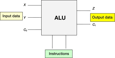
Arithmetic Logic Units (ALUs) are key components in digital systems that perform arithmetic and logical operations on binary data. They are crucial for mathematical calculations, data manipulation, and decision-making processes within a computer or microprocessor. Let’s explore the key aspects of Arithmetic Logic Units:
Introduction to ALUs
An Arithmetic Logic Unit (ALU) is a combinational logic circuit that performs arithmetic operations (such as addition, subtraction, multiplication, and division) and logical operations (such as AND, OR, and XOR) on binary inputs. ALUs are responsible for processing and manipulating numerical and logical data within a digital system.
Operation and Functionality
ALUs receive binary inputs and perform various operations based on control signals. The specific operations to be performed are determined by the instruction set architecture (ISA) of the computer or microprocessor. ALUs typically include circuits for addition, subtraction, logical operations, shifting, and comparison. They can also handle overflow and carry/borrow operations.
Components of an ALU
ALUs consist of several components that work together to execute arithmetic and logical operations. These components may include:
- Binary Adders: Adders are used to perform addition operations within an ALU. They can range from simple half-adders and full-adders to more complex adder circuits like ripple carry adders or carry-lookahead adders.
- Logical Gates: ALUs incorporate logical gates (such as AND, OR, and XOR gates) to perform logical operations on the input data.
- Shifter Circuits: Shifter circuits shift the binary bits left or right to enable shifting operations, such as arithmetic shifts or logical shifts.
- Control Unit: The control unit within an ALU generates the necessary control signals to determine which operation(s) should be executed based on the instruction or operation code.
Applications
ALUs are vital components within microprocessors and digital systems. Some common applications include:
- Central Processing Units (CPUs): ALUs form a critical part of the CPU, executing arithmetic and logical instructions during data processing.
- Calculators and Computers: ALUs perform mathematical computations and logical operations required for tasks ranging from simple calculations to complex data processing.
- Digital Signal Processing (DSP): ALUs play a significant role in DSP applications, performing operations on digital signals for audio processing, image processing, and telecommunications.
- Control Units: ALUs are employed in control units to execute logical decisions and comparisons, enabling control and coordination within a digital system.
Understanding ALUs and their operation is essential for designing and analyzing digital systems that require arithmetic and logical capabilities. By utilizing ALUs effectively, engineers and designers can implement efficient data processing and decision-making functionalities in a wide range of applications.
Memory Units
Memory units are essential components in digital systems that store and retrieve data in electronic devices. They play a vital role in data storage, temporary storage (volatile memory), and permanent storage (non-volatile memory). Let’s explore the key aspects of memory units:
Introduction to Memory Units
Memory units are electronic circuits that provide the ability to store and retrieve digital data. They are crucial for storing instructions, data, and intermediate results within a digital system. Memory units come in different types, each with its own characteristics, capacity, and access times.
Volatile Memory vs. Non-Volatile Memory
Memory units can be categorized into two main types based on data retention:
- Volatile Memory: Volatile memory refers to temporary storage that requires a continuous power supply to retain data. The most common form of volatile memory is Random Access Memory (RAM), which is fast and allows for both reading and writing operations. However, it loses its data when power is removed.
- Non-Volatile Memory: Non-volatile memory retains data even without a power supply. Examples of non-volatile memory include Read-Only Memory (ROM), Electrically Erasable Programmable Read-Only Memory (EEPROM), and Flash Memory. These memory types are used for permanent storage and retain their data even when power is disconnected.
Types of Memory Units
There are several types of memory units commonly used in digital systems:
- Random Access Memory (RAM): RAM allows for fast reading and writing of data. It is used for temporary storage of data and instructions during program execution. RAM can be further classified into Static RAM (SRAM) and Dynamic RAM (DRAM) based on their implementation and characteristics.
- Read-Only Memory (ROM): ROM is a non-volatile memory that stores data and instructions that cannot be modified or erased. It typically contains firmware, boot code, and system configuration information. ROM is used for permanent storage.
- Flash Memory: Flash memory is a type of non-volatile memory that allows for both reading and writing operations. It is commonly used in devices such as USB drives, memory cards, and solid-state drives (SSDs).
- Cache Memory: Cache memory is a high-speed memory unit that resides between the CPU and main memory. It stores frequently accessed data and instructions to reduce the time taken to access data from slower main memory.
- Magnetic Disk Storage: Magnetic disk storage, such as hard disk drives (HDDs), provides large-capacity non-volatile storage for computer systems. It utilizes magnetism to store data on rotating disks.
- Optical Storage: Optical storage, such as CDs, DVDs, and Blu-ray discs, uses laser technology to read and write data on a reflective surface. It offers non-volatile storage with high capacity.
Memory Hierarchy
Memory units are often organized in a hierarchy, with different levels of memory offering varying capacities, speeds, and costs. The memory hierarchy includes registers, cache memory, main memory (RAM), secondary storage (e.g., hard disk drives), and tertiary storage (e.g., optical discs or tape drives). The hierarchy is designed to provide a balance between speed and cost, with faster and more expensive memory closer to the processor.
Applications
Memory units are utilized in various applications, including:
- Computer Systems: Memory units are integral to computer systems, providing storage for operating systems, applications, and data.
- Embedded Systems: Memory units are used in embedded systems, such as microcontrollers and IoT devices, to store program code, configurations, and data.
- Mobile Devices: Memory units are crucial in smartphones, tablets, and other mobile devices for storing user data, applications, and media files.
- Gaming Consoles: Memory units are utilized in gaming consoles to store game data, graphics, and user profiles.
Understanding the different types of memory units and their characteristics is essential for designing efficient and reliable digital systems. By selecting and utilizing the appropriate memory units, engineers and designers can optimize data storage, processing, and retrieval in a wide range of applications.

Programmable Logic Controllers (PLCs)
Programmable Logic Controllers (PLCs) are specialized digital computers used for industrial automation and control systems. They provide a robust and flexible platform for controlling machinery, processes, and equipment in various industries. Let’s explore the key aspects of Programmable Logic Controllers:
Introduction to PLCs
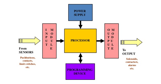
PLCs are electronic devices designed to control and automate industrial processes. They consist of a programmable processor, input/output (I/O) modules, memory, and a programming interface. PLCs are widely used in manufacturing, process control, building automation, and other industries to monitor and control machinery, production lines, and complex systems.
Components of PLCs
PLCs comprise several key components:
- Central Processing Unit (CPU): The CPU is the core of the PLC, responsible for executing control programs, managing I/O operations, and coordinating system functions.
- Input/Output (I/O) Modules: I/O modules serve as the interface between the PLC and the external world. They handle digital and analog signals from sensors, switches, and other devices as inputs, and control actuators, motors, and other devices as outputs.
- Memory: PLCs have different types of memory for storing the control program, data values, and system configurations. These include program memory (ROM or flash memory), data memory (RAM), and non-volatile memory for retaining critical information.
- Programming Interface: PLCs provide a programming interface or software environment where engineers can create, edit, and debug control programs. Programming languages such as ladder logic, structured text, function block diagrams, and sequential function charts are commonly used.
Functionality and Operation
PLCs operate in a cyclic manner, repeatedly executing a control program to monitor inputs, make decisions, and control outputs. They scan the input devices, update the values, execute the control program, and update the output devices accordingly. This process occurs in real-time, allowing for precise control and synchronization of industrial processes.
Advantages of PLCs
PLCs offer several advantages in industrial automation and control:
- Flexibility: PLCs are highly flexible and can be easily programmed and reprogrammed to accommodate changing control requirements and system modifications.
- Reliability: PLCs are designed for robustness and reliability, capable of operating in harsh industrial environments and providing uninterrupted control.
- Modularity and Expandability: PLC systems can be expanded by adding additional I/O modules, allowing for scalability and future system expansion.
- Diagnostics and Troubleshooting: PLCs provide built-in diagnostics, monitoring capabilities, and logging features to aid in system analysis, troubleshooting, and maintenance.
Applications of PLCs
PLCs find applications in various industries and sectors, including:
- Manufacturing: PLCs control assembly lines, robots, conveyors, and material handling systems in manufacturing plants.
- Process Control: PLCs manage and regulate industrial processes such as chemical production, water treatment, power generation, and food processing.
- Building Automation: PLCs are used in building management systems to control HVAC (Heating, Ventilation, and Air Conditioning), lighting, access control, and security systems.
- Transportation: PLCs automate and control systems in transportation infrastructure, including traffic signals, railway control systems, and airport baggage handling.
PLCs have revolutionized industrial automation by providing efficient and reliable control solutions. They enable efficient monitoring, precise control, and improved safety in complex industrial processes.
Finite State Machines (FSMs)
Finite State Machines (FSMs) are mathematical models used to represent systems with discrete states and transitions between these states based on inputs. FSMs provide a structured approach to modeling and analyzing complex systems and are widely used in digital design, control systems, communication protocols, and more. Let’s explore the key aspects of Finite State Machines:
Introduction to FSMs
Finite State Machines are theoretical models that represent systems with a finite number of states, transitions between states, and inputs that trigger state transitions. FSMs are capable of defining and capturing the dynamic behavior of systems, making them essential for designing and analyzing systems that exhibit sequential logic.
Components of FSMs
FSMs consist of several key components:
- States: States represent the distinct conditions or modes that a system can be in. Each state represents a specific behavior, operation, or mode of the system.
- Transitions: Transitions define the movement between states based on inputs. When a specific input occurs, the FSM transitions from the current state to a new state.
- Inputs: Inputs are external signals or events that trigger state transitions. They are essential for determining the behavior of the FSM and which state the machine transitions to.
- Outputs: Outputs are the results or actions associated with specific states or transitions. Outputs may include actions, signals, or data that the FSM generates based on its current state or transition.
Types of FSMs
There are two main types of FSMs:
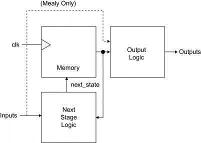
- Mealy Machines: Mealy machines are FSMs where the outputs depend on both the current state and the inputs. The outputs are associated with the transitions between states.
- Moore Machines: Moore machines are FSMs where the outputs depend only on the current state. The outputs are associated with the states themselves.
State Diagrams and State Tables
FSMs can be represented using state diagrams and state tables. State diagrams use circles to represent states and arrows to represent transitions between states triggered by specific inputs. State tables provide a tabular representation, indicating the current state, input conditions, next state, and associated outputs.
Applications of FSMs
FSMs find applications in various domains, including:
- Control Systems: FSMs are used to model and control complex systems such as robots, industrial automation, and electronic control systems.
- Digital Design: FSMs play a vital role in designing digital circuits, sequential logic systems, and digital systems with memory.
- Communication Protocols: FSMs are used to define and implement communication protocols, stateful network protocols, and data transmission protocols.
- Compiler Design: FSMs are utilized in lexical analysis, parsing, and code generation phases of compiler design to model and analyze programming languages.
Understanding FSMs and their applications is essential for designing and analyzing systems that exhibit sequential behavior. By utilizing FSMs effectively, engineers and designers can create efficient, reliable, and well-defined systems in a wide range of applications.
Conclusion
In the blog post “Types of Logics in Electronics,” we explored the fundamental concepts of logic gates, including basic and advanced ones, such as AND, OR, NOT, NAND, NOR, and XOR gates. We discussed how combinational logic circuits use these gates to produce specific logical functions based on the current inputs. Sequential logic circuits, on the other hand, incorporate memory elements to store past inputs and internal state information, allowing for more complex operations. We also explored programmable logic devices (PLDs), which offer the flexibility to implement custom logic functions. By understanding these types of logics, we gain the foundation to design and analyze digital systems effectively. Whether it’s arithmetic operations, process control, or data processing, the knowledge of different logics in electronics empowers us to build innovative solutions in various applications and contribute to technological advancements.
FAQs about Types of Logic
- What are the basic logic gates?
Basic logic gates are the fundamental building blocks of digital circuits and include gates such as AND, OR, NOT, NAND, NOR, and XOR. These gates perform logical operations on binary inputs and produce corresponding output signals.
- What is the difference between combinational logic and sequential logic?
Combinational logic circuits produce output solely based on the current input values, without any internal memory. On the other hand, sequential logic circuits incorporate memory elements, allowing them to store past input values and internal states, resulting in output that depends on both current inputs and previous states.
- How do programmable logic devices (PLDs) work?
Programmable logic devices, such as programmable logic arrays (PLAs), programmable array logic (PAL), and field-programmable gate arrays (FPGAs), allow users to define custom logic functions and interconnections. They can be programmed or reprogrammed to implement specific digital circuits and provide flexibility in design.
- What are the applications of different types of logic in electronics?
The applications of different types of logic in electronics are vast. Basic logic gates are used in various digital systems and electronic devices. Combinational logic circuits are utilized for data processing, control units, and memory addressing. Sequential logic circuits are essential for applications such as memory units, counters, shift registers, and microprocessors.
- How can knowledge of different types of logic benefit electronic design?
Understanding different types of logic enables engineers and designers to analyze, design, and optimize digital systems efficiently. It allows for the implementation of custom logic functions, memory operations, sequential processes, and complex control functions. This knowledge empowers designers to create innovative solutions in areas such as automation, communication systems, signal processing, and computing.
