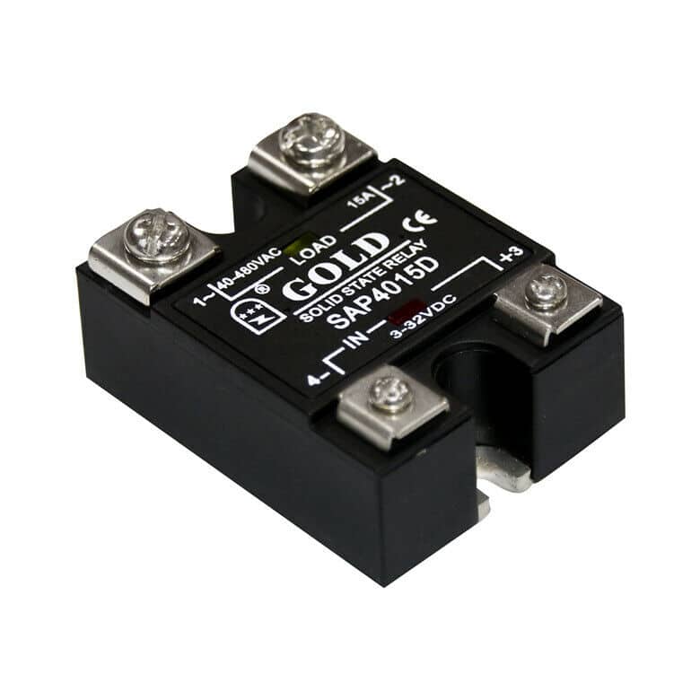
Solid State Relays (SSRs) represent a major advancement in Switches and Relays technology, serving a crucial role in modern electronic systems that often goes unnoticed. Operating as electronic switching devices, SSRs activate or deactivate in response to external voltage signals, seamlessly bridging control circuits and power circuits. With their capacity to switch high-power loads without mechanical parts, SSRs have transformed power distribution across various industries, from industrial automation to aerospace.
The introduction of SSRs in 1971 marked a pivotal development in relay technology. By eliminating moving parts, SSRs introduced a new standard in switching reliability and longevity, paving the way for sophisticated and efficient control systems. This innovation equipped engineers and designers with a solution to meet the demanding needs of contemporary electronic applications.
The significance of Solid State Relays in today’s electronics and power systems cannot be overstated. They have greatly enhanced performance, reliability, and efficiency in numerous applications. Key benefits of SSRs include:
- Extended operational lifespan due to the absence of mechanical wear
- Silent operation, making them ideal for noise-sensitive environments
- Rapid switching speeds for precise control in time-critical applications
- High reliability in high-frequency switching scenarios
- Improved safety with features like zero-crossing switching in AC applications
These advantages have led to the widespread adoption of SSRs across diverse sectors. From industrial process control and HVAC systems to telecommunications and medical equipment, SSRs are now indispensable components. Their versatility enables them to perform exceptionally well in both high-power industrial settings and sensitive electronic devices, establishing them as a cornerstone of modern electronic design alongside other Types of Relays and Types of Rotary Switches.
As technology progresses, SSRs are continually evolving to meet new demands. Modern designs incorporate advanced thermal management, higher voltage and current ratings, and enhanced integration with digital control systems. In the era of Industry 4.0 and smart manufacturing, SSRs are playing an increasingly vital role in enabling precise power control, energy efficiency, and system diagnostics. Despite their seemingly straightforward function, Solid State Relays are essential for ensuring reliable, efficient, and safe operation in our ever-electrified world.
Types of Solid Slate Relays
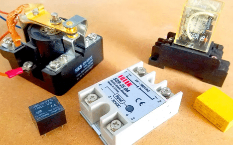
Solid State Relays (SSRs) come in various designs, each tailored to specific applications, environments, and performance requirements. While there are multiple ways to categorize these devices, such as by mounting method, switching characteristic, isolation method, or input/output type, we’ve chosen to focus on the core technology behind the switching elements and the output type. This classification provides a comprehensive understanding of SSR functionality and offers insights into their operational principles and application suitability. Here are the main types of Solid State Relays based on their core technology and output characteristics:
- Thyristor-based SSRs
- MOSFET-based SSRs
- IGBT-based SSRs
- Zero-crossing SSRs
- Random-turn-on SSRs
Each of these SSR types has its own set of characteristics, advantages, and limitations, making them suitable for different applications across various industries. The choice of SSR depends on factors such as switching speed, load type (AC or DC), current and voltage ratings, thermal management requirements, and the specific environment in which the relay will be used.
The importance of this categorization lies in its ability to provide a comprehensive understanding of SSR functionality and operational principles. By focusing on the core technology and output characteristics, this classification offers insights into the fundamental behavior and capabilities of different SSR types. This approach allows for a clear comparison of key performance metrics such as switching speed, power handling capacity, and electromagnetic interference (EMI) characteristics. Furthermore, it provides a solid foundation for understanding the evolution of SSR technology and facilitates informed decision-making in relay selection and system design across various industries and applications.
Types of Solid Slate Relays Specifications in Table
| Category | Types | Key Features | Common Applications | Advantages | Disadvantages | Cost |
| Thyristor-based | Standard, Custom, Hybrid | High voltage/current handling, no moving parts, silent operation | Industrial automation, motor control, lighting | Longevity, fast switching, no arcing, high reliability, compact size | Heat generation, requires heat sinks, sensitive to voltage transients | Moderate |
| MOSFET-based | Standard, High-speed | Fast switching, low on-resistance, efficient for DC loads | Consumer electronics, automotive, telecommunications | Fast switching, low power loss, high efficiency | Limited to DC applications, higher cost than thyristors | Higher |
| IGBT-based | Standard, Ultrafast, Isolation, Low-voltage, High-temperature, Custom | High voltage/current capability, fast switching, isolation options | Motor drives, power supplies, industrial automation | High power handling, fast switching, isolation, suitable for high-power apps | Complex control, higher cost, requires careful thermal management | Higher |
| Zero-crossing | AC switching, DC switching | Switches at zero voltage crossing, reduces EMI/RFI | Lighting control, heating systems, motor control | Reduced EMI/RFI, smooth operation, energy efficient | Limited to specific load types, slower response time | Moderate |
| Random-turn-on | AC-controlled, DC-controlled, EMI/RFI suppression | Immediate switching, suitable for inductive loads | Systems requiring fast response, industrial automation | Fast response, suitable for inductive loads | Higher EMI/RFI, potential for inrush current | Moderate to High |
What are Thyristor-based SSRs?
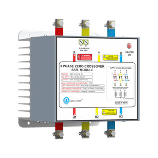
Thyristor-based Solid State Relays (SSRs) are electronic switching devices that employ thyristors, semiconductor components known for controlling electrical loads efficiently. Unlike traditional electromechanical relays, these SSRs operate without moving parts, enhancing reliability and lifespan. At the core of these relays is the thyristor, commonly a Silicon Controlled Rectifier (SCR), which allows switching of high power with a small control signal. Thyristor-based SSRs are particularly well-suited for high-power applications, ranging from a few to several hundred amperes, and are often used in AC load switching due to their natural turn-off capability at the AC zero-crossing point.
These relays consist of key components: an input circuit to receive control signals, an isolation mechanism (like optocouplers), the thyristor switching element, and protective components such as snubber circuits. Thyristor-based SSRs are valued for their fast switching speeds and high reliability, making them indispensable in industrial automation, power control systems, and other high-power applications requiring precise switching.
Working Principle of Thyristor-based SSRs
The operation of thyristor-based SSRs relies on the unique properties of thyristors. Let’s break down the working principle into more detailed steps:
- Input signal: A low-power control signal (typically 3-32V DC or AC) is applied to the input terminals of the SSR, usually provided by a microcontroller, PLC, or another control system.
- Isolation: The input signal is electrically isolated from the output circuit using an optocoupler, which consists of an LED and a phototransistor. This provides galvanic isolation, ensuring safety and preventing electrical interference between the control and power circuits.
- Triggering: The isolated signal from the optocoupler is used to trigger the gate of the thyristor. In AC applications, a zero-crossing detection circuit may be employed to trigger at the zero-crossing point of the AC waveform, minimizing electromagnetic interference. The gate current required is small compared to the load current.
- Conduction: Once triggered, the thyristor conducts current through the load and continues even if the gate signal is removed, as long as the current remains above the holding current level. In AC applications, this conduction continues until the current naturally drops below the holding current level at each zero-crossing.
- Turn-off: In AC applications, the thyristor turns off automatically when the current drops below the holding current level at the zero-crossing point. In DC applications, additional circuitry, such as forced commutation, may be required to turn off the thyristor.
- Heat Management: During conduction, the thyristor generates heat due to its internal resistance. Most SSRs include a metal baseplate for heat dissipation, and external heat sinks may be required in high-power applications.
- Protection: Snubber circuits, typically RC networks, protect the thyristor from rapid voltage changes (dV/dt) that could trigger it unintentionally. Overvoltage protection devices, such as metal oxide varistors (MOVs), are often included to guard against voltage spikes.
This working principle allows for rapid and precise switching of high-power loads with minimal wear and tear on the device, making thyristor-based SSRs ideal for applications requiring frequent switching or handling of high inrush currents.
Applications of Thyristor-based SSRs
Thyristor-based Solid State Relays (SSRs) are widely used in various industries due to their durability, fast switching, and ability to handle high-power loads. Their versatility and efficiency make them ideal for applications that require precise control, minimal electromagnetic interference, and long operational life. Below are some of the key industries and applications where these relays are indispensable:
- Industrial Automation: Used in manufacturing processes for precise control of machinery and equipment.
- HVAC Systems: Employed for efficient temperature regulation in heating and cooling systems.
- Power Distribution: Utilized in smart grids for load management and power factor correction.
- Renewable Energy: Integral in solar inverters and wind turbine control systems.
- Automotive Industry: Used in electric vehicle charging stations and battery management systems.
- Medical Equipment: Applied in MRI machines and other sensitive medical devices for noise-free operation.
- Lighting Control: Implemented in both industrial and residential settings for advanced dimming and switching.
- Consumer Electronics: Incorporated in home appliances for improved energy efficiency and longevity.
Types of Thyristor-based SSRs
Thyristor-based Solid State Relays (SSRs) utilize various thyristor types as their main switching elements, classified by their turn-on and turn-off behavior, voltage and current characteristics, and directionality of control. The primary types include:
- SSRs with Turn-on Capability (Unidirectional Control):
- Silicon Controlled Rectifier (SCR) SSRs: Widely used, these SSRs remain latched even when gate current is removed and turn off when anode current drops to zero or becomes negative. Applications include switching circuits and DC motor drives.
- Reverse Conducting Thyristor (RCT) SSRs: Integrate an SCR with a reverse diode for improved commutation and reduced undesired inductance. Used in inverters and high-power choppers.
- Light-Activated Silicon-Controlled Rectifier (LASCR) SSRs: Activated by light, providing electrical isolation. Used in HVDC transmission and high-power pulse generators.
- SSRs with Turn-off Capability (Unidirectional Control):
- Gate Turn-Off Thyristor (GTO) SSRs: Can be turned off with a negative gate signal, making them suitable for DC and AC motor drives.
- MOS Turn-Off Thyristor (MTO) SSRs: Combine GTO and MOSFET technologies for improved performance, used in high-voltage systems and motor drives.
- Emitter Turn-Off Thyristor (ETO) SSRs: Feature a normal and a MOSFET-controlled gate, ideal for high-power inverters.
- SSRs with Bidirectional Control:
- Triode for Alternating Current (TRIAC) SSRs: Conduct current in both directions, commonly used in light dimmers and fan speed controls.
- Diode for Alternating Current (DIAC) SSRs: Low-power devices ensuring even TRIAC triggering, used in light bulb dimmers.
- Silicon Diode for Alternating Current (SIDAC) SSRs: Operate similarly to DIACs but with higher power handling, useful in relaxation oscillators.
- Custom and Hybrid Thyristor SSRs: These combine different thyristor types for specific performance needs, including additional components for enhanced control or efficiency.
Each type of thyristor-based SSR offers distinct advantages based on the application’s voltage, current handling capabilities, and other requirements.
Advantages of Thyristor-based SSRs
Thyristor-based SSRs offer numerous benefits over traditional electromechanical relays:
- Longevity: With no moving parts, they have a significantly longer operational life.
- Silent Operation: The absence of mechanical switching eliminates clicking noises.
- Fast Switching: They can switch on and off much faster than mechanical relays.
- No Arcing: The solid-state design eliminates contact arcing, enhancing safety and reducing electromagnetic interference.
- High Reliability: They are less susceptible to shock, vibration, and environmental factors.
- Compact Size: Generally smaller than equivalent mechanical relays, allowing for space-saving designs.
- Compatibility with Control Systems: Easy integration with modern digital control and automation systems.
- Energy Efficiency: Lower power consumption in the control circuit and more efficient switching of loads.
Disadvantages of Thyristor-based SSRs
Despite their many advantages, thyristor-based SSRs also have some limitations:
- Heat Generation: They produce more heat than mechanical relays, often requiring heat sinks or additional cooling.
- Voltage Drop: There’s a small voltage drop across the device when conducting, which can be an issue in some applications.
- Cost: Generally more expensive than equivalent mechanical relays, especially for high-power applications.
- Susceptibility to Voltage Transients: They can be damaged by voltage spikes if not properly protected.
- Leakage Current: A small current may flow even when the SSR is in the off state, which can be problematic in some sensitive applications.
- Limited Overload Capacity: They typically can’t handle large overloads as well as some mechanical relays.
- Complexity: The internal circuitry is more complex than mechanical relays, potentially making troubleshooting more difficult.
What are MOSFET-based SSRs?
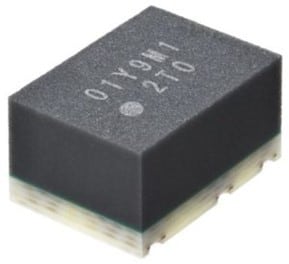
MOSFET-based Solid State Relays (SSRs) are highly advanced switching devices that rely on Metal-Oxide-Semiconductor Field-Effect Transistors (MOSFETs) to control electrical loads. Unlike traditional electromechanical relays, MOSFET-based SSRs have no moving parts, resulting in greater reliability, faster switching speeds, and longer lifespans. These relays incorporate optical isolation between the input and output circuits, ensuring complete electrical separation and enhancing safety. The solid-state design of MOSFET SSRs allows them to handle both AC and DC loads efficiently, making them suitable for a variety of applications.
One of the key advantages of MOSFET-based SSRs is their ability to perform bidirectional switching, often achieved by using two MOSFETs in a back-to-back configuration for AC control. They are compact and energy-efficient, requiring minimal control power to manage larger output loads. Additionally, they often come equipped with integrated protection features such as overvoltage and overcurrent safeguards, further enhancing their durability and performance in industrial and commercial environments.
Working Principle of MOSFET-based SSRs
The working principle of MOSFET-based Solid State Relays (SSRs) involves several key steps:
- Input Signal: A low-current control signal, typically from a microcontroller or other control circuit, is applied to the SSR’s input. This signal requires very little power, often as low as 1.5V DC, allowing direct integration with logic-level circuits. The low power consumption of the input stage is a major advantage, making MOSFET SSRs efficient for use in modern low-power control systems.
- Optical Coupling: The input signal activates an LED within the SSR, emitting infrared light. The LED provides fast and reliable switching while electrically isolating the control and output sides of the relay. This optical isolation enhances noise immunity and safety by preventing electrical feedback.
- Voltage Generation: The emitted light reaches a photovoltaic diode (PVD), generating a small voltage through the photovoltaic effect. This voltage, although minimal, is enough to control the MOSFET gates while preserving electrical isolation.
- MOSFET Activation: The voltage from the PVD triggers the gates of back-to-back MOSFETs, creating a low-resistance path for current flow. MOSFETs’ fast switching and low on-resistance are critical for the relay’s performance.
- Load Switching: The MOSFETs either allow current to flow (ON state) or block it (OFF state). In AC applications, back-to-back MOSFETs handle bidirectional current flow, ensuring efficient load control across both positive and negative cycles.
In a typical configuration for AC switching, two N-channel MOSFETs are connected back-to-back with their sources tied together. This arrangement allows for bidirectional current flow when the relay is ON and blocks current in both directions when OFF.
For AC applications:
- During positive half-cycles, current flows through one MOSFET and the body diode of the other.
- During negative half-cycles, the current path is reversed.
Some MOSFET SSRs include an internal drive controller to accelerate gate discharge when switching off, ensuring smooth and reliable operation. This controller can help manage issues like Miller effect capacitance, which can affect switching speed and reliability.
Applications of MOSFET-based SSRs
MOSFET-based Solid State Relays (SSRs) are increasingly employed across a diverse array of industries due to their exceptional efficiency, reliability, and rapid switching capabilities. These devices play a vital role in modern applications where precise control and durability are paramount. Notably, some of the key applications can be found in the following sectors:
- HVAC Systems: For efficient temperature control and energy management.
- Industrial Automation: In programmable logic controllers (PLCs) and process control systems.
- Automotive Electronics: For various control systems in modern vehicles.
- Semiconductor Testing Equipment: Leveraging their high-speed switching capabilities.
- Battery Management Systems: For electric vehicles and renewable energy storage.
- Audio Equipment: Where low noise operation is crucial.
- Instrumentation Systems: For precise control and measurement applications.
- Uninterruptible Power Supplies (UPS): For reliable power switching.
- Smart Home Devices: In thermostats, lighting controls, and other IoT devices.
- Medical Equipment: Where reliability and electrical isolation are critical.
Types of MOSFET-based SSRs
MOSFET-based Solid State Relays (SSRs) are versatile devices designed to accommodate a wide range of applications, offering fast switching, high efficiency, and reliable performance. These relays utilize MOSFETs to manage electrical loads with minimal power loss and heat generation. The various types of MOSFET-based SSRs are classified based on their switching behavior, voltage, current capacity, and packaging. Below are the key variations explained in detail:
- Make and Break Types: “Make” type relays are normally open, closing the circuit when activated, while “Break” type relays are normally closed and open the circuit when activated.
- ON/Depletion and OFF/Enhancement Types: ON/Depletion types can be used as normally closed relays, while OFF/Enhancement types function as normally open relays, suitable for different control needs.
- AC and DC Switching Types: AC switching SSRs are designed for alternating current loads, whereas DC switching SSRs are optimized for handling direct current applications.
- Voltage Ranges: Low-voltage SSRs are designed for loads up to 60V, medium-voltage SSRs operate between 60V and 300V, and high-voltage SSRs can handle loads exceeding 300V.
- Current Ratings: Low current SSRs manage currents up to 5A, medium current SSRs handle between 5A and 40A, while high current SSRs switch loads above 40A.
- Packaging Types: Through-hole packages are suitable for traditional PCB mounting, surface mount packages are ideal for high-density assemblies, and panel mount types are used in control panels for easy integration.
Advantages of MOSFET-based SSRs
MOSFET-based SSRs offer numerous benefits over traditional electromechanical relays:
- Fast Switching: Operate significantly faster than mechanical relays.
- Silent Operation: No clicking or mechanical noise during switching.
- Long Lifespan: No mechanical wear, leading to extended operational life.
- High Reliability: Resistant to shock, vibration, and environmental factors.
- Low Power Consumption: Require minimal input power to control high-power loads.
- Compact Size: Generally smaller and lighter than equivalent mechanical relays.
- No Contact Bounce: Eliminates issues related to contact arcing and wear.
- Compatibility with Control Systems: Easy integration with modern digital systems.
- Wide temperature range: Stable operation across varying environmental conditions.
- Electrical Isolation: Complete isolation between input and output circuits.
Disadvantages of MOSFET-based SSRs
Despite their many advantages, MOSFET-based SSRs also have some limitations:
- Higher Initial Cost: Generally more expensive than equivalent mechanical relays.
- Heat Generation: Can produce more heat than mechanical relays, potentially requiring heat sinks.
- On-State Resistance: Even when fully on, there’s a small voltage drop across the device.
- Vulnerability to Voltage Transients: Can be damaged by large voltage spikes if not properly protected.
- Leakage Current: A small current may flow even when the SSR is in the off state.
- Limited Overload Capacity: Generally can’t handle large overloads as well as some mechanical relays.
- Complexity: Internal circuitry is more complex, potentially making troubleshooting more difficult.
- EMI Generation: Can produce electromagnetic interference, especially in AC switching applications.
- Unidirectional Control: Unlike some mechanical relays, most SSRs can only control current in one direction.
- Temperature Sensitivity: Performance can be affected by extreme temperatures.
What are IGBT-based SSRs?
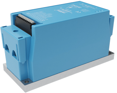
IGBT-Based Solid State Relays (SSRs) are sophisticated switching devices that leverage Insulated Gate Bipolar Transistors (IGBTs) as their primary switching element. These relays facilitate the conversion of low-power control inputs into high-current gate drives for internal or external power switches, enabling low-power control over high-power signals while ensuring galvanic isolation between the logic circuitry and the high-power signals. IGBT-based SSRs are distinguished by their ability to combine the high input impedance and rapid turn-on speed of MOSFETs with the low conduction losses characteristic of bipolar junction transistors (BJTs). This unique combination makes IGBT-based SSRs particularly well-suited for applications that demand high voltage and current handling capabilities, typically operating at frequencies ranging from 1 to 50 kHz. Key features include a solid-state design with no moving parts, which enhances durability and extends lifespan compared to traditional electromechanical relays. Many IGBT SSRs also incorporate optical isolation between input and output for added safety and reduced electrical noise interference. These relays are commonly employed in various applications, including motor control, power supplies, and industrial automation, where high performance, reliability, and efficient operation are essential.
Working Principle of IGBT based SSRs
IGBT-based SSRs operate on a principle that combines voltage-controlled switching with current amplification. Here’s a more detailed explanation of the process:
- Input signal: A low-power control signal (typically 3-5V DC) is applied to the input side of the SSR. This signal is usually generated by a microcontroller, PLC, or other control circuitry.
- Isolation: The input signal is electrically isolated from the output circuit, typically using an optocoupler. This optical isolation ensures safety and prevents noise from the high-power circuit from affecting the low-power control circuit.
- Gate drive: The isolated signal is amplified by a gate driver circuit, which generates the appropriate voltage and current to control the IGBT’s gate. The gate driver ensures fast and efficient switching of the IGBT.
- IGBT operation: The IGBT itself consists of a MOSFET input stage and a bipolar transistor output stage. When a positive voltage is applied to the gate:
- The MOSFET channel turns on, allowing current to flow.
- This current acts as the base current for the bipolar transistor section.
- The bipolar transistor amplifies this current, allowing for high current flow between the collector and emitter.
- Switching: When the gate voltage exceeds the threshold voltage (typically 3-5V), the IGBT turns on, allowing current to flow through the main power circuit. The IGBT enters saturation mode, where it exhibits low voltage drop (1-2V) even at high currents.
- Turn-off: When the input signal is removed, the gate driver quickly removes the gate charge. However, due to the bipolar transistor portion, there’s a tail current during turn-off as excess carriers recombine. This results in a slightly longer turn-off time compared to MOSFETs.
- Protection features: Many IGBT-based SSRs include additional circuits for overvoltage protection, overcurrent protection, and temperature monitoring to ensure safe operation.
Applications of IGBT based SSRs
IGBT-based SSRs find applications in various industries and systems, including:
- Variable speed motor control
- Switch-mode power supplies (SMPS)
- DC-AC inverters
- Electric vehicles and traction motor control
- Renewable energy systems (solar inverters, wind turbines)
- Induction heating equipment
- Welding machines
- Uninterruptible Power Supplies (UPS)
- Pulse-width modulation (PWM) AC and DC motor drives
- Frequency converters
- Industrial furnaces and ovens
- Power factor correction circuits
Types of IGBT-Based SSRs
IGBT-based Solid State Relays (SSRs) are available in various types, each tailored to meet distinct application needs. The most common categories include:
- Standard IGBT SSRs: These versatile relays are suitable for a wide array of applications, such as motor control, lighting, and heating. They provide an excellent balance of performance characteristics for typical industrial and commercial uses. High-voltage IGBT SSRs are designed for applications requiring the handling of elevated voltage levels, particularly in power distribution or high-voltage equipment control. Meanwhile, high-current IGBT SSRs can manage significant current loads, making them ideal for power supply systems and large motor drives.
- Ultrafast IGBT SSRs: Optimized for rapid switching, these relays excel in applications necessitating precise control and quick response times, such as frequency converters, inverters, and high-power audio amplifiers.
- Isolation IGBT SSRs: Offering galvanic isolation between control and load circuits, these relays ensure safety and minimize electrical interference, commonly used in industrial automation.
- Low-voltage IGBT SSRs: Designed for lower voltage applications, they are suitable for consumer electronics and small-scale industrial equipment.
- High-temperature IGBT SSRs: Engineered for extreme thermal conditions, they maintain performance in harsh environments.
- Custom IGBT SSRs: Tailored to meet specific requirements, these relays optimize performance for specialized applications, accommodating unique voltage, current, or environmental needs.
Each type of IGBT SSR presents specific advantages, selected based on the application’s voltage and current handling requirements, switching speed, isolation needs, environmental conditions, and any special features necessary for optimal performance.
Advantages of IGBT based SSRs
IGBT-based SSRs offer several advantages:
- High voltage and current handling capability: Suitable for high-power applications, with typical voltage ratings around 1400V.
- Fast switching speed: Faster than electromechanical relays, with switching times in the microsecond to millisecond range.
- Low on-state voltage: Results in minimal power losses and improved overall system efficiency.
- High input impedance: Easily driven by low-power control signals, reducing the complexity of drive circuitry.
- Long lifespan: No mechanical wear and tear, resulting in extended operational life compared to electromechanical relays.
- Silent operation: No audible noise during switching.
- Compact size: Smaller footprint compared to equivalent electromechanical relays.
- Enhanced conductivity: Due to the bipolar nature of IGBTs.
- Safety: Improved safety features compared to some other switching technologies.
- High current density: Enables a smaller chip size for the same current and voltage ratings.
Disadvantages of IGBT based SSRs
Despite their many advantages, IGBT-based SSRs also have some limitations:
- Limited frequency range: Less suitable for very high-frequency applications due to intrinsic capacitance and switching losses.
- Gate drive complexity: Requires more complex gate drive circuits compared to simpler switching technologies.
- Heat generation: IGBTs produce heat during operation, requiring proper thermal management.
- Voltage transients: May experience voltage spikes during switching, necessitating appropriate snubber circuits and protection mechanisms.
- Unidirectional current flow: Standard IGBTs only conduct current in one direction, requiring additional components for AC applications.
- Higher cost: Generally more expensive than BJTs and MOSFETs.
- Potential for latch-up: Due to the PNPN structure similar to thyristors.
- Longer turn-off times: Compared to PMOS transistors.
- Limited reverse voltage blocking: Cannot handle high reverse voltages without additional circuitry.
What are Zero-crossing SSRs?
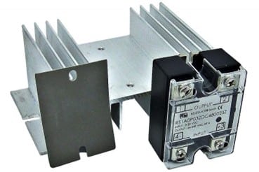
Zero-crossing Solid State Relays (SSRs) are specialized electronic switching devices designed to activate only when the alternating current (AC) voltage waveform passes through the zero point. Unlike random turn-on SSRs that switch immediately upon receiving a control signal, Zero-crossing SSRs incorporate a built-in zero-cross detection circuit that waits for the next zero-voltage point in the AC cycle before activating. These devices are engineered to minimize electromagnetic interference, reduce inrush currents, and extend the lifespan of both the relay and the connected load. By switching at or near the zero-voltage point, Zero-crossing SSRs significantly reduce electrical stress on components and suppress switching noise. Zero-crossing SSRs are particularly well-suited for resistive and slightly inductive loads. They find widespread use in various applications, including heating systems, lighting control, and industrial process control. However, it’s important to note that they may not be suitable for highly inductive loads or DC applications. It’s worth noting that Zero-crossing SSRs could be categorized under other types of SSRs based on their semiconductor technology (such as thyristor-based or IGBT-based). However, due to their unique switching characteristics and widespread use, it’s beneficial to discuss Zero-crossing SSRs as a separate category.
Working Principle of Zero-crossing SSRs
The working principle of Zero-crossing SSRs can be broken down into several key steps:
- Input Signal Reception: The SSR receives a control signal to turn on.
- Zero-cross Detection: Instead of switching immediately, the SSR’s internal circuit monitors the AC load voltage.
- Waiting Period: The SSR waits for the AC voltage to approach the zero-crossing point (when voltage is closest to 0V).
- Switching Action: When the zero-crossing is detected, the SSR activates its power switching component (usually a thyristor or TRIAC).
- Load Energization: The load is connected to the power source at or near the zero-voltage point, minimizing switching transients.
- Turn-off Process: When the control signal is removed, the SSR typically waits for the next zero-crossing of the load current before turning off.
This process ensures that switching occurs when voltage and current are at their minimum, reducing electrical stress on both the SSR and the connected load.
Applications of Zero-crossing SSRs
Zero-crossing SSRs find applications in various industries and systems, including:
- Heating Systems: Temperature control in industrial ovens, furnaces, and HVAC systems.
- Lighting Control: Dimming and switching of resistive lighting loads.
- Motor Soft Starters: Reducing inrush current in motor starting applications.
- Power Supplies: Switching of transformer primaries in power supply units.
- Industrial Process Control: Precise control of resistive and slightly inductive loads.
- Home Appliances: Energy-efficient control in modern household devices.
- Renewable Energy Systems: Inverter and power management in solar and wind energy systems.
- Medical Equipment: Reliable switching in sensitive medical devices.
Types of Zero-Crossing SSRs
Zero-crossing Solid State Relays (SSRs) can be classified based on several factors:
Power Handling Capacity:
- Low-power SSRs are suitable for small signal lamps and electronic devices.
- Medium-power SSRs are suitable for household appliances and general-purpose industrial applications.
- High-power SSRs are suitable for large industrial processes and heavy machinery.
Control Input Type:
- DC-controlled SSRs are triggered by direct current signals.
- AC-controlled SSRs are triggered by alternating current signals.
Load Voltage Rating:
- Low-voltage SSRs are suitable for low-power electronics.
- Medium-voltage SSRs are suitable for household applications.
- High-voltage SSRs are suitable for heavy industrial settings.
Packaging:
- PCB-mount SSRs are suitable for compact designs.
- Panel-mount SSRs are suitable for control panels.
- DIN-rail mount SSRs are suitable for easy installation in industrial cabinets.
Number of Poles:
- Single-pole SSRs are suitable for simple on/off control.
- Three-pole SSRs are suitable for three-phase applications in motor control.
Semiconductor Technology:
- Thyristor-based SSRs are the most common type.
- TRIAC-based SSRs are suitable for bidirectional flow.
- IGBT-based SSRs are suitable for high-power applications.
Additional Considerations:
- Isolation: Zero-crossing SSRs provide electrical isolation between the control input and the load output.
- Response Time: The response time of a zero-crossing SSR depends on the type of semiconductor technology used and the load characteristics.
- Heat Sink: High-power SSRs may require a heat sink to dissipate excess heat.
Advantages of Zero-crossing SSRs
Zero-crossing SSRs offer several benefits:
- Reduced Electromagnetic Interference (EMI): By switching at zero voltage, they minimize electrical noise generation.
- Lower Inrush Current: Helps protect both the SSR and the load from high current spikes.
- Extended Service Life: Reduced stress on components leads to longer operational life.
- Improved Reliability: Consistent switching at zero-crossing enhances overall system stability.
- Quiet Operation: No audible switching noise, unlike mechanical relays.
- Compatibility with Resistive Loads: Ideal for heaters, lamps, and other resistive loads.
- No Contact Bounce: Eliminates issues associated with mechanical relay contacts.
- Fast Response: While waiting for zero-crossing, the actual switching is very quick.
- No Arcing: Eliminates the risk of contact welding or arcing seen in mechanical relays.
- Compact Size: Generally smaller than equivalent mechanical relays.
Disadvantages of Zero-crossing SSRs
Despite their advantages, Zero-crossing SSRs have some limitations:
- Limited Load Types: Not ideal for highly inductive loads or capacitive loads.
- Potential for Surge Currents: If switching doesn’t occur exactly at zero volts, small surge currents can occur.
- Inrush Current Issues: With certain loads (e.g., incandescent lamps), inrush current can still be a problem.
- Thermal Management: Requires proper heat sinking to manage heat generation.
- Cost: Generally more expensive than mechanical relays or random turn-on SSRs.
- Leakage Current: Small current may flow even when the SSR is off.
- Vulnerability to Voltage Transients: May require additional protection circuits.
- Complexity: More complex than simple mechanical relays, potentially requiring specialized knowledge for troubleshooting.
- Not Suitable for DC Loads: Zero-crossing principle only applies to AC applications.
- Slight Delay in Activation: The wait for zero-crossing can introduce a small delay in switching.
What are Random-turn-on SSRs?
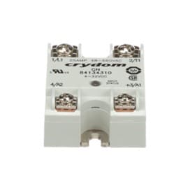
Random-turn-on Solid State Relays (SSRs) are electronic switches that activate immediately upon receiving a control signal, regardless of the AC voltage’s position in the waveform. Unlike zero-crossing SSRs, which wait for the voltage to cross zero before switching to minimize electrical noise, random-turn-on SSRs can engage at any point in the AC cycle. This capability allows for a faster response time, making these relays ideal for applications where immediate power delivery is critical, such as phase angle control, light dimming, or motor speed regulation. Due to their ability to switch instantly, random-turn-on SSRs are well-suited for controlling inductive loads like transformers, motors, or solenoids, which may not respond optimally to zero-cross switching. However, because they can turn on at any point in the voltage cycle, they may generate more electromagnetic interference (EMI), leading to electrical noise or surges in sensitive systems. As a result, these SSRs are often chosen when quick switching is a priority, but they may require additional filtering or mitigation measures to address potential EMI issues.
Working Principle of Random-turn-on SSRs
The working principle of random-turn-on SSRs is straightforward:
- Control Signal Reception: The SSR receives a control voltage at its input terminals.
- Immediate Activation: Upon receiving the control signal, the SSR turns on within a very short time, typically less than 100 microseconds.
- Load Energization: The load is connected to the power source at the instant the SSR activates, regardless of the AC waveform’s current phase.
- Turn-off Process: When the control signal is removed, the SSR turns off when the current goes through zero.
The turn-on point is determined by the timing of the control signal applied to the relay’s input, allowing for more precise control in certain applications.
Applications of Random-turn-on SSRs
Random-turn-on SSRs find applications in various industries and systems, including:
- Phase Control Circuits: Where precise timing control is required.
- Inductive Load Switching: Such as motors, compressors, and transformers.
- Three-Phase Systems: Where simultaneous switching of all phases is desirable.
- General-purpose Switching: For applications that can tolerate some level of inrush current or transient noise.
- Lighting Control: In situations where precise dimming or flicker-free operation is not critical.
- Heating and Cooling Systems: Where the load can handle potential inrush current.
- Systems Requiring Immediate Switching: Applications where fast response time is crucial.
Types of Random-Turn-On Solid-State Relays (SSR)
While random-turn-on SSRs generally do not have specific subtypes based on their turn-on mechanism, they can be classified based on other factors, similar to zero-crossing SSRs. These factors include:
- Power Handling Capacity: Low, medium, and high-power ratings.
- Control Input Type: DC-controlled or AC-controlled.
- Load Voltage Rating: Low, medium, and high-voltage ratings.
- Packaging: PCB-mount, panel-mount, and DIN-rail mount.
- Number of Poles: Single-pole and three-pole.
- Semiconductor Technology: Thyristor-based, TRIAC-based, or IGBT-based.
Additional Considerations:
- EMI/RFI Suppression: Some random-turn-on SSRs may incorporate built-in EMI/RFI suppression circuitry to mitigate interference.
- Inrush Current Limiting: Certain models may have features to limit the inrush current to the load.
- Surge Protection: Some SSRs may be designed with surge protection to withstand transient voltage spikes.
Note: While the classification of random-turn-on SSRs based on these factors is similar to zero-crossing SSRs, the key difference lies in their turn-on mechanism. Random-turn-on SSRs do not have a specific zero-crossing detection mechanism and can turn on at any point during the AC cycle.
Advantages of Random-turn-on SSRs
- Faster Response Time: Can react more quickly to control signals compared to zero-crossing SSRs.
- Lower Cost: Generally less expensive than zero-crossing SSRs due to simpler design.
- Simpler Internal Structure: Easier to manufacture and potentially more reliable.
- Suitable for Inductive Loads: Recommended for switching inductive loads like motors and transformers.
- Precise Timing Control: Allows for phase control applications where exact switching timing is crucial.
- Immediate Switching: Ideal for systems requiring instantaneous response to control signals.
- Versatility: Suitable for a wide range of applications where zero-crossing is not critical.
Disadvantages of Random-turn-on SSRs
- Potential for EMI/RFI: Can generate electromagnetic interference or radio frequency interference due to non-synchronized turn-on.
- Inrush Current: May cause higher inrush current to the load, potentially stressing components.
- Less Precise Control for Certain Loads: Not suitable for applications requiring careful control of turn-on timing to minimize electrical stress.
- Electromagnetic Noise: Can create more electromagnetic noise when switching, which may interfere with sensitive electronic equipment.
- Not Ideal for Resistive Loads: Zero-crossing SSRs are often preferred for purely resistive loads to minimize switching transients.
- Potential for Voltage Spikes: The random turn-on can lead to voltage spikes in certain applications, requiring additional protection circuits.
- Less Energy Efficient: In some cases, the non-synchronized switching can lead to slightly higher power losses compared to zero-crossing SSRs.
Understanding these characteristics of random-turn-on SSRs is crucial for engineers and designers to select the most appropriate switching solution for their specific application, balancing factors such as response time, load type, and electromagnetic compatibility requirements.
Conclusion
Solid State Relays (SSRs) have emerged as a pivotal component in modern electronic systems, offering numerous advantages over traditional electromechanical relays. Their increased operational lifespan, silent operation, and rapid switching speeds make them ideal for a wide range of applications, from industrial process control and HVAC systems to telecommunications and medical equipment. The absence of mechanical wear and the ability to handle high-frequency switching scenarios enhance their reliability and safety, particularly through features like zero-crossing switching in AC applications. As a result, SSRs have become indispensable in both high-power industrial settings and sensitive electronic devices, underscoring their versatility and importance in contemporary electronic design.
As technology advances, SSRs continue to evolve, incorporating improved thermal management, higher voltage and current ratings, and enhanced integration with digital control systems. In the context of Industry 4.0 and smart manufacturing, SSRs play a crucial role in enabling precise power control, energy efficiency, and system diagnostics. Despite their seemingly simple function, SSRs remain at the forefront of ensuring reliable, efficient, and safe operation in our increasingly electrified world. However, challenges such as heat generation, susceptibility to voltage transients, and higher costs compared to mechanical relays must be addressed to fully leverage their potential. Overall, SSRs are poised to remain a cornerstone of modern electronic systems, adapting to meet the demands of future technological advancements.
FAQs about Solid State Relays
- What are the main advantages of using Solid State Relays over electromechanical relays?
Solid State Relays offer several advantages, including increased operational lifespan due to the absence of mechanical wear, silent operation, rapid switching speeds, enhanced reliability in high-frequency switching scenarios, and improved safety through features like zero-crossing switching in AC applications. - In which applications are Solid State Relays commonly used?
SSRs are widely used in various applications such as industrial process control, HVAC systems, telecommunications, medical equipment, smart home devices, renewable energy systems, automotive industry, and power distribution in smart grids. - What are some of the challenges or limitations associated with Solid State Relays?
Some challenges include heat generation requiring heat sinks, susceptibility to voltage transients, leakage current even when off, limited overload capacity, and higher cost compared to mechanical relays. - How do Solid State Relays manage heat generation during operation?
SSRs typically include a metal baseplate for heat dissipation, and in high-power applications, external heat sinks may be required. Proper thermal management is crucial to ensure reliable operation. - What types of Solid State Relays are available based on switching and voltage requirements?
SSRs are available in AC and DC switching types, with voltage ranges categorized as low-voltage (up to 60V), medium-voltage (60V to 300V), and high-voltage (exceeding 300V). They also come in various packaging types such as through-hole, surface mount, and panel mount.
